| t
| Torque wrench -V.A.G 1331- |

WARNING | Before removing the steering column, please note the following points: |
| t
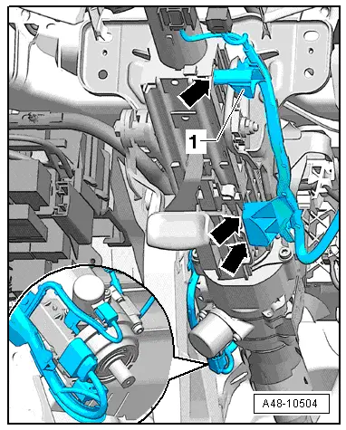
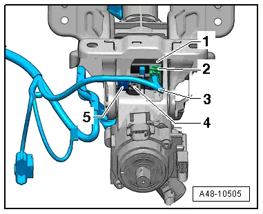
| the layout of the electrical wiring harnesses |
| t
| the attachment of the electrical wiring harnesses |
| t
| the fitting locations of the cable ties. |
| This applies particularly to the wiring harness for the electronic steering column lock control unit -J764-. |
| Before installing the steering column, please note the following points: |
| l
| Restore the layout of the electrical wiring harnesses exactly as it was prior to removal. |
| l
| Restore the attachments of the electrical wiring harnesses exactly as they were prior to removal. |
| l
| All cable ties unfastened or cut open when removing the steering column must be re-attached in the same position when refitting it. |
| l
| When adjusting the steering column, check that the wiring harness leading to the electronic steering column lock control unit -J764- is not trapped and does not come into contact with any sharp edges. |
|

Note | t
| The replacement steering column is only supplied as a complete unit. Repair is not possible. |
| t
| Only the electronic steering column lock control unit -J764- can be renewed separately. |
| –
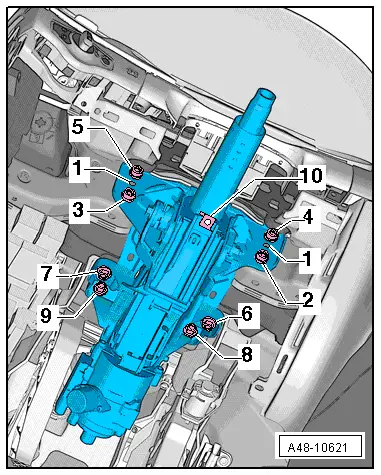
| Turn wheels to straight ahead position. |
| –
| Move steering wheel downwards and rearwards as far as possible, using the full range of the steering column adjuster. |
| –
| If fitted, remove bracket for right knee bolster (driver side) → Rep. gr.68. |
WARNING | On steering columns for dynamic steering: never slacken or remove the bolts of the dynamic steering unit. |
|
|
|
|