| –
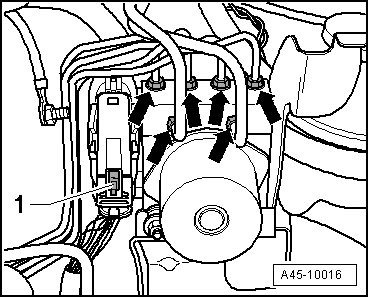
| Press down retainer catch -1- so it engages. |
| –
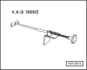
| Remove brake pedal actuator -V.A.G 1869/2-. |
| –
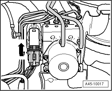
| Perform final control diagnosis after securing brake lines to hydraulic unit -N55-. |

Note | Final control diagnosis can be used to establish whether line connections have been interchanged. |
| Use vehicle diagnosis and service information system -VAS 5051B- or -VAS 5052- to do this. |
| If a new ABS control unit -J104- has been fitted, it must be encoded. |
| Use vehicle diagnosis and service information system -VAS 5051B- or -VAS 5052-. |
| t
| 001 - Self-diagnosis compatible systems |
| t
| 003 - Brake electronics |
| –
| Select required function on the display: |
| t
| J104 Control unit for ABS/ASR/ESP |
| t
| J104 Control unit for ABS/ASR/ESP, functions |
| Also calibrate the following senders after renewing control unit -J104-. |
| t
| Steering angle sender -G85- |
| t
| Lateral acceleration sender -G200- |
| t
| Longitudinal acceleration sender -G251- |
| Use vehicle diagnosis and service information system -VAS 5051B- or -VAS 5052-. |
| t
| 001 - Self-diagnosis compatible systems |
| t
| 003 - Brake electronics |
| –
| Select required function on the display: |
| t
| J104 Control unit for ABS/ASR/ESP |
| t
| J104 Control unit for ABS/ASR/ESP, functions. |
| –
| Then carry out ESP road test and system test. |
|
|
|
 Caution
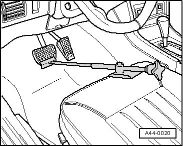
 WARNING