
A5
| Transmission layout |
| Identification and ratio |
 Note
Note| Arrows point in direction of travel. |
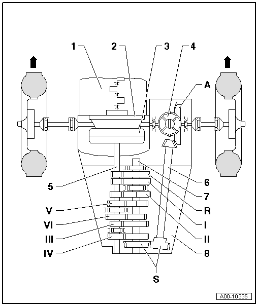
| 1 - | Engine |
| 2 - | Drive plate |
| q | With needle bearing for gearbox input shaft |
| 3 - | Clutch module |
| q | Consists of pressure plate, clutch plate and dual-mass flywheel with flange for drive plate |
| 4 - | Differential |
| 5 - | Input shaft (main shaft) |
| 6 - | Pinion shaft (side shaft) |
| 7 - | Output shaft |
| 8 - | Manual gearbox |
| I - | 1st gear |
| II - | 2nd gear |
| III - | 3rd gear |
| IV - | 4th gear |
| V - | 5th gear |
| VI - | 6th gear |
| R - | Reverse gear |
| A - | Final drive |
| S - | Spur gears (intermediate drive) |
| q | With beveloid teeth |