
A5
| Removing gearbox - vehicles with 4-cyl. petrol engine |
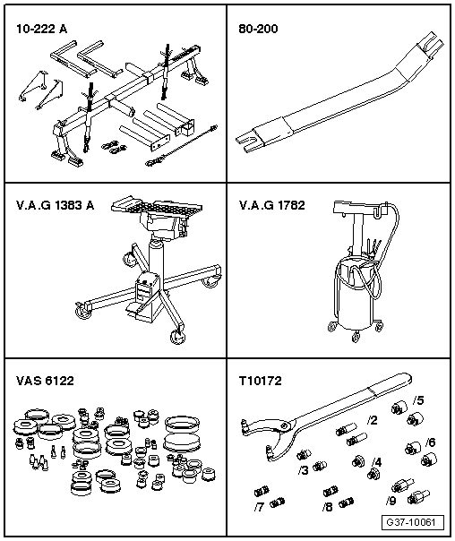
| Special tools and workshop equipment required |
| t | Removal lever -80 - 200- |
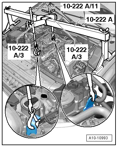
| t | Support bracket -10 - 222 A- |
| t | Engine and gearbox jack -V.A.G 1383 A- |
| t | Used oil collection and extraction unit -V.A.G 1782- |
| t | Engine bung set -VAS 6122- |
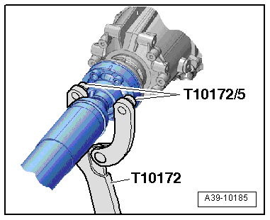
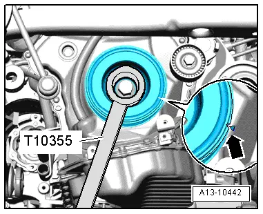
| t | Counterhold tool -T10172- with -T10172/5- |
|
|
|
|
|
|
|
|
|
|
 Caution
 Note
Note
|
|
|
|
Note
|
|
Note
Note |
|
|
|
|
|
|
|
|
|
Note
|
|
|
|
|
|
|
|
|
|
Note
|
|
|
|
Note
|
|
Note
Note
|
|
Note
|
|
|
|
|
|
|
|
|
|
|
|
|
|
|
|
|
|
Note
|
|
|
|
|
|
Note
|
|
|
|
|
|
Note
|
|