audi Workshop Repair Guides

Audi Workshop Service and Repair Manuals

Final drive, differential, differential lock > < Exploded view - input shaft with friction plates
Removing and installing hydraulic control unit
Removing
  Note
t  → Chapter „Repair instructions“.
t  → Chapter „Rules for cleanliness when working on the gearbox“.
l  End cover must be removed → Chapter.
l  Automatic gearbox control unit -J217- must be removed → Chapter.
   
  Caution
There is a risk of damage to the spring.
t  Do not use sharp pliers or similar when inserting or removing spring.
t  The detent for the selector shaft will no longer function properly if the wire of the spring is damaged by incision or kinking.
–  Unhook spring -1- from lever for selector shaft detent -2- and from selector shaft -3-.
  A38-10185
–  Swivel lever for selector shaft detent -1- to right -arrow- so that retaining tab -A- is rotated out of slot on retaining plate -B-.
  A38-10186
–  Pull lever for selector shaft detent -1- downwards out of hole in housing of hydraulic control unit. Pay attention to the roller -2- when doing this.
  A38-10187
–  Remove bolts -arrows-.
  Caution
Take care not to damage hydraulic control unit.
t  NEVER suspend or lift the hydraulic control unit by the long pump shaft on the rear side of the hydraulic control unit!
t  This would distort the vanes inside the vane pump and damage the pump. There is also a risk of damaging the bearing of the pump shaft.
–  Carefully pull hydraulic control unit out towards rear and then tilt it downwards so that the long pump shaft can be guided out.
  Note
Item -A- can be disregarded.
  A38-10188
–  Remove axial sealing elements -A- and -B- from gearbox.
Installing
Installation is carried out in reverse sequence; note the following:
l  Tightening torques → Chapter „Exploded view - end cover, automatic gearbox control unit -J217-, hydraulic control unit“
  Note
t  Always renew contaminated or defective hydraulic control units.
t  Renew gaskets and O-rings.
–  Renew axial sealing elements -A- (3x) and -B-.
  A38-10189
l  Installation position: axial sealing elements -A- must be inserted with sealing lips facing upwards, as shown in sectional illustration.
l  The coloured mark on the top edge must be visible.
–  Coat axial sealing elements with ATF and insert in direction of -arrow-.
  A38-10175
–  Push gearbox selector lever -2- all the way to the front in direction of -arrow- until shifting cam -1- is almost vertical (with a slight inclination to the left).
  A38-10189
–  Push control piston -B- on reverse side of hydraulic control unit outwards (to the right) until it clips into securing spring -A-.
–  Tilt hydraulic control unit downwards and insert it into gearbox, long pump shaft first.
  Note
When fitting the hydraulic control unit, make sure the shifting cam (-item 1- in illustration above → Anchor) engages in the vacant groove -arrow- on the control piston -B-.
  Caution
Take care not to damage hydraulic control unit.
The hydraulic control unit will be damaged if the shifting cam or the control piston are not in the correct position and the bolts are already tightened to torque in the following step.
  A38-10190
–  Screw in bolts -arrows- hand-tight.
  A38-10188
Checking operation of control piston
–  Move gearbox selector lever -A- forward and back several times -arrow 1-.
l  The control piston -B- should travel in and out accordingly -arrow 2-.
  A38-10191
If control piston fails to move this means that shifting cam has not engaged in groove -arrow- of control piston on reverse side of hydraulic control unit. In that case:
–  Detach hydraulic control unit again.
  A38-10190
Check for damage due to incorrect installation:
l  It must be possible to slide control piston -B- smoothly to left and right; if not, hydraulic control unit must be renewed.
l  There must not be any damage to shifting cam -1- or selector shaft due to incorrect installation.
–  Insert hydraulic control unit again → Anchor.
  A38-10189
If it is possible to move control piston as described:
–  Tighten bolts -arrows- to torque.
  A38-10188
Installing lever for selector shaft detent
–  Push roller -2- onto lever for selector shaft detent -1- (with collar facing lever for selector shaft detent).
–  Push lever for selector shaft detent -1- into hole in housing of hydraulic control unit.
  A38-10187
–  Swivel lever for selector shaft detent -1- to left in opposite direction of -arrow- so that retaining tab -A- is rotated into slot on retaining plate -B- and engages.
  Caution
There is a risk of damage to the spring.
t  Do not use sharp pliers or similar when inserting or removing spring.
t  The detent for the selector shaft will no longer function properly if the wire of the spring is damaged by incision or kinking.
  A38-10186
–  Hook spring -1- into selector shaft -3- and lever for selector shaft detent -2-.
Installation position of spring -1-:
l  Bent end of spring must be hooked into selector shaft -3-.
l  Round end of spring must be hooked into lever for selector shaft detent -2-.
  A38-10185
–  Shift gearbox selector lever -A- forward and back as far as it will go -arrow 1-.
  Note
-Arrow 2- and item -B- can be disregarded.
  A38-10191
l  
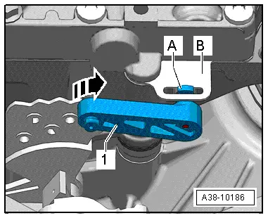
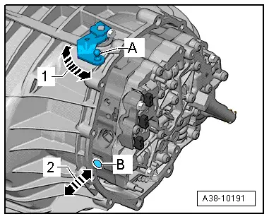
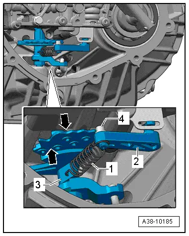
The detent plate -top arrow- moves to the left and right.
l  As it moves, the roller -4- should be able to engage in the individual notches one-by-one.
l  
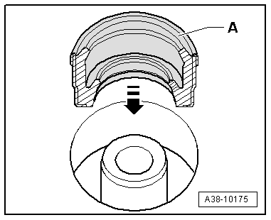
Roller must be installed with the collar pointing downward, so that it cannot be pulled off upwards.
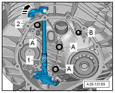
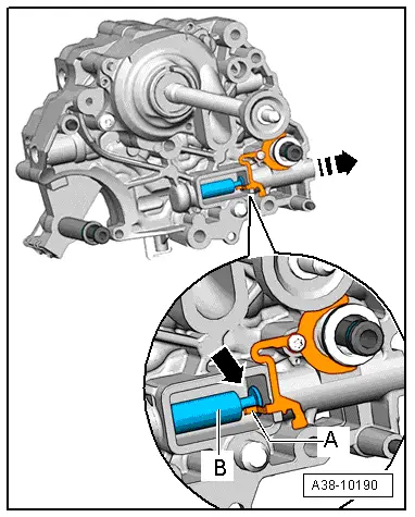
–  Install automatic gearbox control unit -J217- → Chapter.
  Caution
If the hydraulic control unit has been renewed, carry out the following steps using a vehicle diagnostic tester:
–  Using the diagnostic tester in Guided Fault Finding mode, go to Function/Component Selection and select the following menu items:
t  Drive system
t  0AW gearbox
t  01 - Self-diagnosis-compatible systems
t  02 - Gearbox electronics
t  02 - Gearbox electronics, Functions
t  02 - Replace hydraulic control unit
  A38-10185

Final drive, differential, differential lock > < Exploded view - input shaft with friction plates