
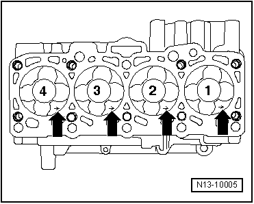
A5
| Pistons and conrods - exploded view |
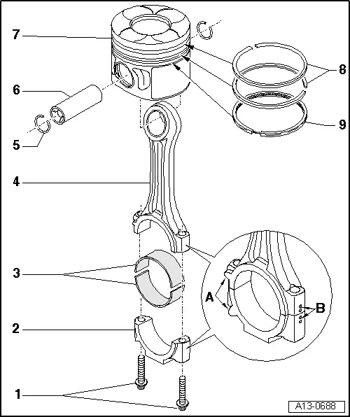
| 1 - | Bolt |
| q | Renew |
| q | Lubricate threads and contact surface |
| q | 30 Nm + turn 90° further |
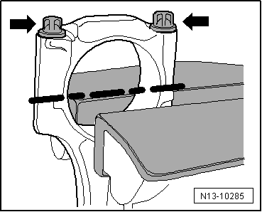
| 2 - | Conrod bearing cap |
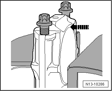
| q | Due to the cracking method used to separate the bearing cap from the conrod in manufacture, the caps only fit in one position and only on the appropriate conrod |
| q | Mark cylinder allocation in colour -B- |
| q | Installation position: Markings -A- face towards pulley end |
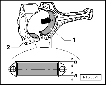
| 3 - | Bearing shell |
| q | Installation position → Fig. |
| q | Renew used bearing shells |
| q | Note version: Upper bearing shell (closest to piston) is constructed from a more wear-resistant material. Distinguishing feature on new bearing shells: black marking on bearing surface near joint |
| q | Check that it is securely seated |
| 4 - | Conrod |
| q | Only renew as a complete set |
| q | With industrially cracked conrod bearing cap |
| q | Separating parts of new conrod → Fig. |
| q | Mark cylinder allocation in colour -B- |
| q | Installation position: Markings -A- face towards pulley end |
| q | Axial clearance: wear limit: 0.37 mm |
| q | Measuring radial clearance → Chapter |
| 5 - | Circlip |
| q | Renew |
| 6 - | Piston pin |
| q | If difficult to move, heat piston to approx. 60 °C |
| q | Remove and install using drift -VW 222 A- |
| 7 - | Piston |
| q | With combustion chamber |
| q | Version fitted in vehicle may differ from illustration |
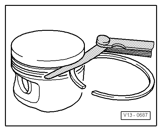
| q | Mark installation position and cylinder number → Fig. |
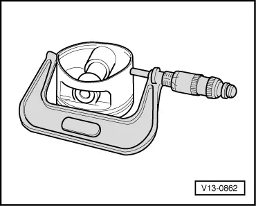
| q | Checking → Fig. |
| q | Install using piston ring clamp |
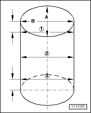
| q | Piston and cylinder dimensions → Chapter |
| q | Measuring cylinder bore → Fig. |
| q | Measuring piston projection at „TDC“ → Chapter |
| 8 - | Piston rings |
| q | Compression rings |
| q | Offset gaps by 120° |
| q | Use piston ring pliers to remove and install |
| q | Installation position: marking „TOP“ or side with lettering faces towards piston crown |
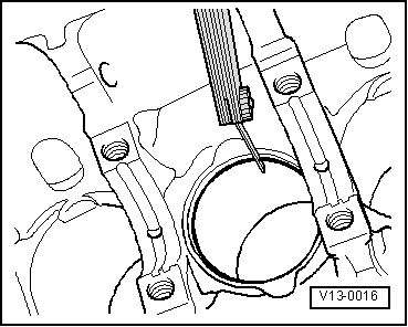
| q | Measuring ring gap → Fig. |
| q | Measuring ring-to-groove clearance → Fig. |
| 9 - | Piston ring |
| q | Oil scraper ring |
| q | Offset gap 120° from bottom compression ring |
| q | Use piston ring pliers to remove and install |
| q | Measuring ring gap → Fig. |
| q | Measuring ring-to-groove clearance → Fig. |
| Piston ring | new mm | Wear limit mm |
| 1st compression ring | 0.25 … 0.40 | 1.00 |
| 2nd compression ring | 0.25 … 0.40 | 1.00 |
| Oil scraper ring | 0.25 … 0.50 | 1.00 |
|
|
| Piston ring | new mm | Wear limit mm |
| 1st compression ring | 0.06 … 0.09 | 0.25 |
| 2nd compression ring | 0.05 … 0.08 | 0.25 |
| Oil scraper ring | 0.03 … 0.06 | 0.15 |
 Note
Note
|
|
|
|
|
|
|
|
|
|
|
|
|
|
 Caution