audi Workshop Repair Guides

Audi Workshop Service and Repair Manuals

Securing engine to engine and gearbox support > < Removing and installing engine - vehicles with manual gearbox
Separating engine and dual clutch gearbox 0B5
Special tools and workshop equipment required
t  Support set for Audi -VAS 6131/10-, support -VAS 6131/13-7- and gearbox support -VAS 6131/14-
   
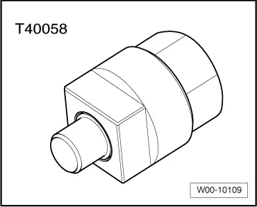
t  Adapter -T40058-
  W00-10109
Procedure
l  Engine/gearbox assembly removed and secured to scissor-type assembly platform -VAS 6131 A-
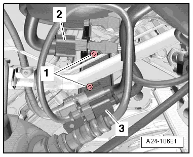
–  Remove electrical connector -3- for Lambda probe 2 after catalytic converter -G131- from bracket and unplug connector.
  Note
Disregard -items 1, 2-.
  A24-10681
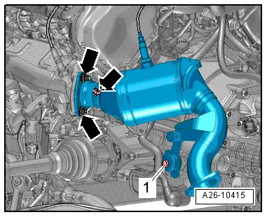
–  Remove bolt -1- and nuts -arrows- and detach catalytic converter (left-side).
  A26-10415
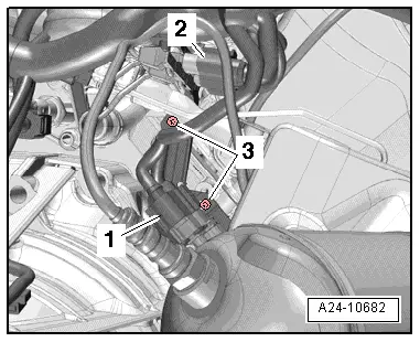
–  Remove electrical connector -1- for Lambda probe after catalytic converter -G130- from bracket and unplug connector.
–  Remove bolts -3- and move bracket clear to one side.
  Note
Disregard -item 2-.
  A24-10682
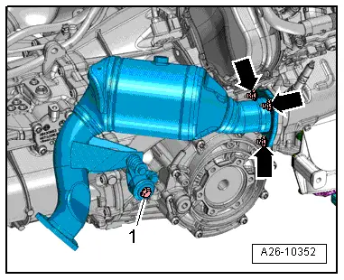
–  Remove bolt -1- and nuts -arrows- and detach catalytic converter (right-side).
  A26-10352
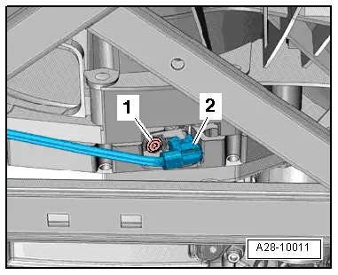
–  Unplug electrical connector -2- at engine speed sender -G28- and move wiring clear.
  Note
Disregard -item 1-.
  A28-10011
Vehicles with electromechanical power steering:
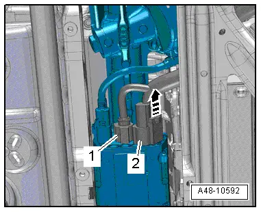
–  Unplug electrical connector -2- at power steering control unit -J500- (release retainer -arrow- and press down release catch).
–  Move clear electrical wiring harness.
  Note
Disregard -item 1-.
  A48-10592
All vehicles (continued):
  Caution
Risk of irreparable damage to gearbox control unit (mechatronic unit) because of static discharge.
Do NOT touch connector contacts in gearbox connector with your hands.
–  Touch gearbox housing with your hand (without wearing gloves) to eliminate static charge.
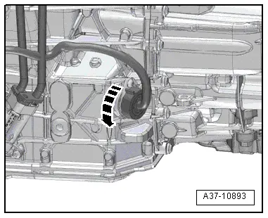
–  Turn retainer catch anti-clockwise -arrow- and unplug electrical connector at gearbox.
–  Move clear electrical wiring harness at gearbox.
  A37-10893
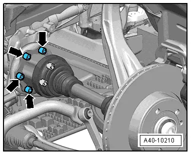
–  Unbolt drive shafts (left and right) from gearbox flange shafts.
  A40-10210
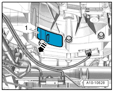
–  Detach bottom cover -1- from gearbox -arrow-.
  A10-10628
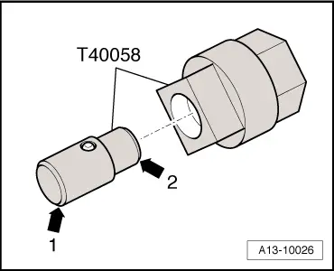
–  Insert guide pin of adapter -T40058- as follows:
l  The larger-diameter section -arrow 1- faces towards the engine.
l  The smaller-diameter section -arrow 2- faces the adapter.
  A13-10026
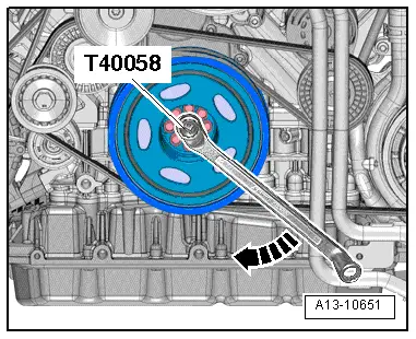
–  Counterhold crankshaft using adapter -T40058- and angled ring spanner when loosening bolts for drive plate.
  Note
Only rotate crankshaft in direction of engine rotation -arrow-.
  A13-10651
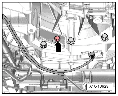
–  Remove 6 bolts -arrow- for clutch module. Turn crankshaft each time by 60° in direction of engine rotation.
  A10-10629
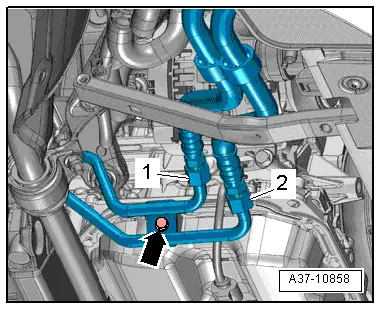
–  Remove bolt -arrow- for ATF lines.
  Note
Disregard -items 1, 2-.
  A37-10858
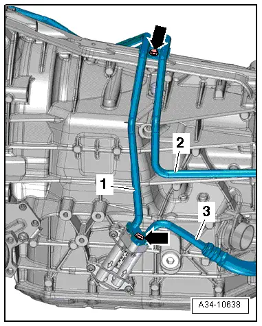
Vehicles with ATF lines (version 1):
  Note
Lay a cloth under the separating point to catch escaping ATF.
–  Remove bolts -arrows- and detach ATF line -1- from gearbox.
  Note
Disregard -items 2, 3-.
  A34-10638
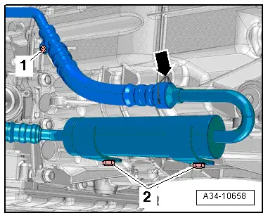
–  Remove bolt -1-.
–  Pull out securing clip -arrow- and disconnect ATF line from ATF filter.
  Note
Disregard -item 2-.
  A34-10658
–  Tie up ATF lines -1- and -2-.
  Note
Disregard -item 3-.
–  Seal off open pipes/lines and connections with clean plugs from engine bung set -VAS 6122-.
  A34-10638
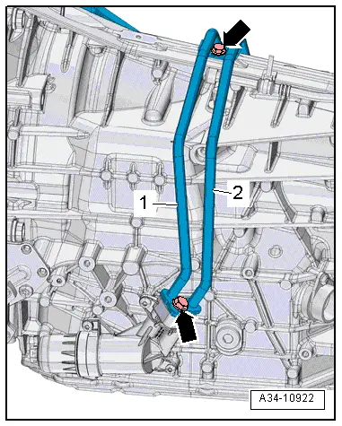
Vehicles with ATF lines (version 2):
  Note
Lay a cloth under the separating point to catch escaping ATF.
–  Unscrew bolts -arrows -, detach ATF lines -1, 2- from ATF-filter housing and tie up ATF lines.
–  Seal off open pipes/lines and connections with clean plugs from engine bung set -VAS 6122-.
  A34-10922
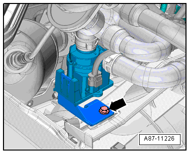
–  Remove bolt -arrow- and move coolant circulation pump -V50- clear to one side.
  A87-11226
All vehicles (continued):
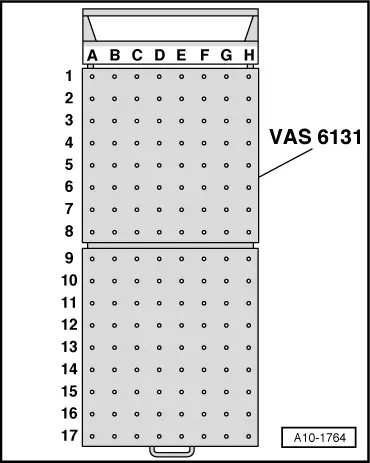
–  Set up scissor-type assembly platform -VAS 6131 A- with support set for Audi -VAS 6131/10-, support -VAS 6131/13-7- and gearbox support -VAS 6131/14- as follows:
  Note
The other support elements remain unchanged.
  A10-1764
Platform coordinatesParts from support set for Audi -VAS 6131/10-, support -VAS 6131/13-7- and gearbox support -VAS 6131/14-
F2/13-7
B10/10-1/10-2/10-5/14
G10/10-1/10-2/10-5

   
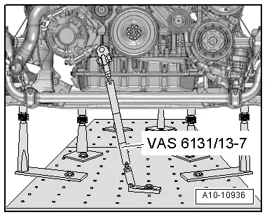
–  Secure support -VAS 6131/13-7- at tapped hole at front of engine (right-side) as illustrated.
–  Secure support -VAS 6131/13-7- to scissor-type assembly platform and tighten to 20 Nm.
  A10-10936
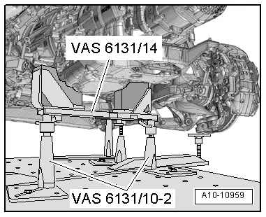
–  Position support elements from -VAS 6131/10- and gearbox support -VAS 6131/14- at front of gearbox, as illustrated.
–  Screw spindles on both sides upwards until gearbox support -VAS 6131/14- makes full contact with gearbox.
–  Tighten base plates for support elements to 20 Nm on scissor-type assembly platform -VAS 6131 A-.
  A10-10959
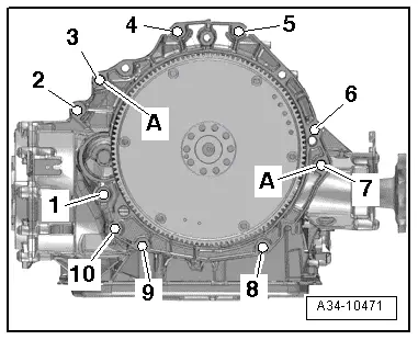
–  Remove bolts -1- and -2- for starter.
–  Separate starter from gearbox and leave in position.
–  Unscrew remaining bolts -3 ... 10- securing engine to gearbox.
  Note
Disregard -item A-.
  A34-10471
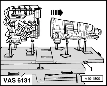
–  Loosen clamping bolts -1- on sides of scissor-type assembly platform -VAS 6131 A- and pull rear section of platform together with gearbox towards rear -arrow-.
  A10-1800

Securing engine to engine and gearbox support > < Removing and installing engine - vehicles with manual gearbox