
A5
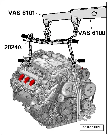
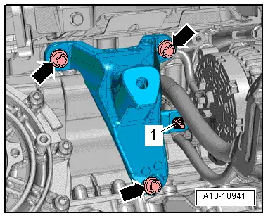
| Securing engine to engine and gearbox support |

| Special tools and workshop equipment required |
| t | Lifting tackle -2024 A- |
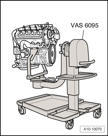
| t | Engine and gearbox support -VAS 6095- with universal mounting -VAS 6095/1- and bracket for V6 FSI engine, Audi A6 -VAS 6095/1-5- |
| t | Workshop hoist -VAS 6100- |
| t | Lift arm extension (workshop hoist) -VAS 6101- |
|
 WARNING
 Note
Note |
|
Note
|
|
Note
|
|
Note
|
|
Note
|
|
Note
|
|
|
|
|
|
|
|
|
|