audi Workshop Repair Guides

Audi Workshop Service and Repair Manuals

Removing and installing coolant pipe (rear right) - engine codes CAMA, CAMB, CAPA > < Removing and installing coolant pipe (top right)
Removing and installing coolant pipe (bottom right)
Special tools and workshop equipment required
   
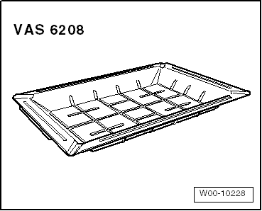
t  Drip tray for workshop hoist -VAS 6208- for vehicles with auxiliary heater
  W00-10228
Removing
–  Drain coolant → Chapter.
–  Remove front right wheel.
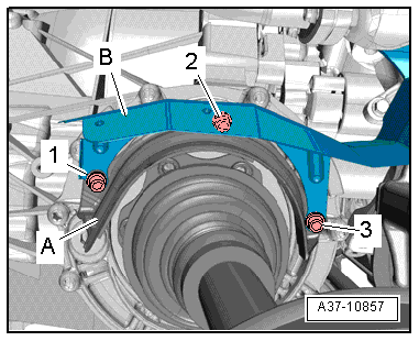
–  Remove bolts -1, 2, 3- and detach heat shield -A- for drive shaft (right-side).
–  Move heat shield -B- clear to one side.
  A37-10857
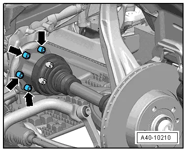
–  Detach drive shaft (right-side) from flange shaft of gearbox → Rep. gr.40.
  A40-10210
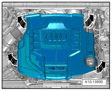
–  Remove engine cover panel -arrows-.
  A10-10890
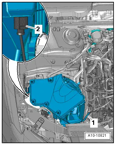
–  Remove air cleaner housing → Rep. gr.23.
  A10-10821
Vehicles with auxiliary heater:
  Caution
Take care to keep components clean.
Observe rules for cleanliness when working on the fuel supply system → Chapter.
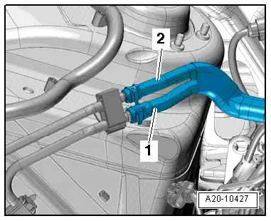
–  Disconnect fuel supply hose -1- and fuel return hose -2-.
  A20-10427
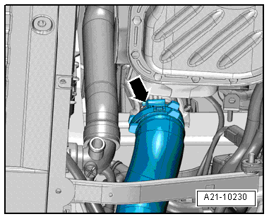
–  Release hose clip -arrow-, disconnect air hose from air pipe and move to one side.
  A21-10230
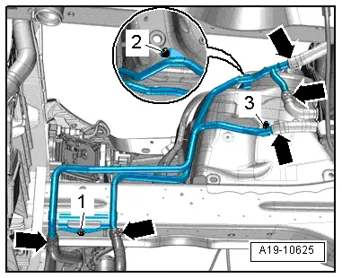
–  Remove bolt -1- and nuts -2- and -3-.
–  Place drip tray for workshop hoist -VAS 6208- beneath engine.
–  Detach coolant hoses -arrows- and swivel coolant pipes towards the front.
  Note
For illustration purposes, the installation position is shown with the engine removed.
  A19-10625
Vehicles with plug-in connector on longitudinal member:
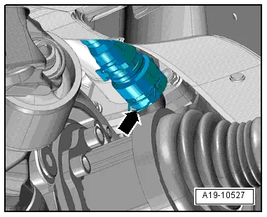
–  Lift retaining clip -arrow- and detach coolant hose from coolant pipe (bottom right).
  A19-10527
All vehicles (continued):
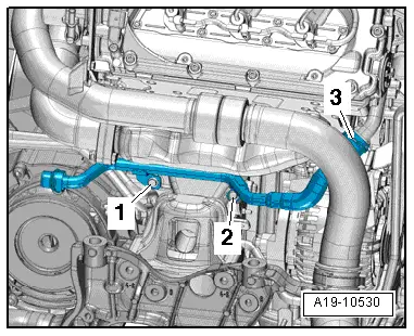
–  Remove bolts -1- and -2-.
–  Lift retaining clip and detach coolant hose -3- from coolant pipe (front).
–  Detach coolant pipe (bottom right).
Installing
Installation is carried out in the reverse order; note the following:
l  Tightening torque → Chapter
  Note
t  Hose connections and air pipes and hoses must be free of oil and grease before assembly.
t  Secure all hose connections with the correct type of hose clips (same as original equipment) → Electronic parts catalogue.
t  To ensure that the air hoses can be properly secured at their connections, spray rust remover onto the worm thread of used hose clips before installing.
–  Connect coolant hose with plug-in connector to coolant pipe → Fig..
–  Install air cleaner housing and exhaust gas pressure sensor 1 -G450- → Rep. gr.23.
–  Secure drive shaft (right-side) to flange shaft of gearbox → Rep. gr.40.
–  Install heat shield for drive shaft → Rep. gr.39.
–  Fit front wheel → Rep. gr.44.
–  Fill up with coolant → Anchor.
  A19-10530

Removing and installing coolant pipe (rear right) - engine codes CAMA, CAMB, CAPA > < Removing and installing coolant pipe (top right)