audi Workshop Repair Guides

Audi Workshop Service and Repair Manuals

Coolant pipes > < Oil pump and sump (bottom section)
Draining and filling cooling system
   
Draining and filling cooling system
Special tools and workshop equipment required
t  Adapter for cooling system tester -V.A.G 1274/8-
t  Pipe for cooling system tester -V.A.G 1274/10-
t  Hose clip pliers -VAS 6362-
t  Cooling system charge unit -VAS 6096-
t  Drip tray for workshop hoist -VAS 6208-
t  Refractometer -T10007-

Draining
  Note
Collect drained coolant in a clean container for re-use or disposal.
  WARNING
Hot steam/hot coolant can escape - risk of scalding.
t  The cooling system is under pressure when the engine is hot.
t  To allow pressure to dissipate, cover filler cap on coolant expansion tank with cloth and open carefully.
–  Open filler cap on coolant expansion tank.
   
–  Remove noise insulation panels -1- and -2- → Rep. gr.66.
  A10-11071
–  Place drip tray for workshop hoist -VAS 6208- beneath engine.
–  Remove drain plug -arrow- at connection and drain off coolant.
  A19-10525
–  Release hose clip -arrow-, disconnect coolant hose from coolant pipe (left-side) and drain off coolant.
  A19-10526
–  Remove cover -1- for drive shaft in wheel housing (right-side).
  A10-10179
–  Vehicles with plug-in connector at coolant pipe (bottom right): Lift retaining clip, disconnect coolant hose -arrow- and drain off coolant.
  A19-10527
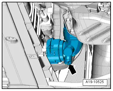
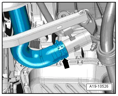
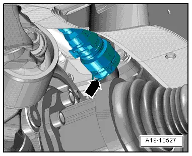
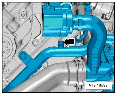
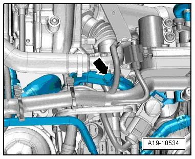
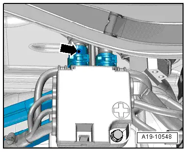
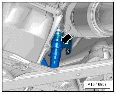
–  Vehicles with plug-in connector at longitudinal member: Lift retaining clip -arrow-, disconnect coolant hose and drain off coolant.
Filling
l  Ignition off.
  Note
t  The cooling system is filled all year round with a mixture of water and coolant additive. Mixture ratio → Anchor
t  Use only the coolant additive listed in the → Electronic parts catalogue. Other coolant additives could seriously impair in particular the anti-corrosion properties. The resulting damage could lead to loss of coolant and consequently to serious engine damage.
t  The specified coolant (based on recommended mixture ratio) → Anchor prevents frost and corrosion damage and stops scaling. Such additives also raise the boiling point of the coolant. For these reasons the cooling system must be filled all year round with the correct coolant additive.
t  Because of its high boiling point, the coolant improves engine reliability under heavy loads, particularly in countries with tropical climates.
t  Frost protection is required down to about –25 °C (in countries with arctic climate: down to about –35 °C).
t  The coolant concentration must not be reduced by adding water even in warmer seasons and in warmer countries. The coolant concentration must be at least 40 %.
t  If greater frost protection is required for reasons of climate, the coolant concentration can be increased up to a maximum of 60% (this gives frost protection down to about –40 °C). Otherwise frost protection decreases again and cooling efficiency also becomes worse.
t  Use only clean tap water for mixing coolant.
t  If radiator, heat exchanger, cylinder head, cylinder head gasket or cylinder block have been renewed, do not re-use old coolant.
t  Contaminated or dirty coolant must not be used again.
t  
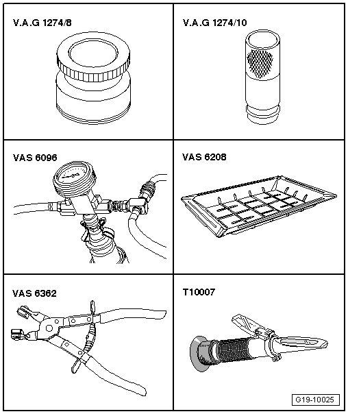
To check anti-freeze protection in cooling system, use refractometer -T10007-.
t  Secure all hose connections with the correct type of hose clips (same as original equipment) → Electronic parts catalogue.
Recommended mixture ratio for coolant
l  Coolant additive (40 %) and water (60 %) for frost protection to –25 °C
l  Coolant additive (50 %) and water (50 %) for frost protection to –35 °C
l  Coolant additive (60 %) and water (40 %) for frost protection to –40 °C
t  Coolant additive → Electronic parts catalogue
  A19-10908
Procedure
–  Vehicles with plug-in connector at coolant pipe (bottom right): Connect coolant hose → Fig..
  A19-10527
–  Vehicles with plug-in connector at longitudinal member: Connect coolant hose → Fig..
  A19-10908
–  Connect coolant hose to coolant pipe (left-side) -arrow-.
  A19-10526
–  Fit drain plug -arrow- with new O-ring into connection.
  A19-10525
–  Fill reservoir of cooling system charge unit -VAS 6096- with at least 12 litres of premixed coolant (according to recommended ratio):
–  Fit adapter for cooling system tester -V.A.G 1274/8- onto coolant expansion tank.
–  Attach cooling system charge unit -VAS 6096- to adapter -V.A.G 1274/8-.
–  Run vent hose -1- into a small container -2-.
  Note
The vented air draws along a small amount of coolant, which should be collected.
–  Close both valves -A- and -B- (turn lever at right angles to direction of flow).
–  Connect hose -3- to compressed air.
l  Pressure: 6 ... 10 bar.
  A19-0351
–  Open valve -B- by setting lever in direction of flow.
l  The suction jet pump generates a partial vacuum in the cooling system; the needle on the gauge should move into the green zone.
–  Also briefly open valve -A- (turn lever in direction of flow) so that hose on reservoir of -VAS 6096- can fill with coolant.
–  Close valve -A- again.
–  Leave valve -B- open for another 2 minutes.
l  The suction jet pump continues to generate a partial vacuum in the cooling system; the needle on the gauge should remain in the green zone.
–  Close valve -B-.
l  The needle on the gauge should stop in the green zone. The vacuum level in the cooling system is then sufficient for subsequent filling.
  Note
t  If the needle does not reach the green zone, repeat the process.
t  Check cooling system for leaks if the vacuum is not maintained.
–  Detach compressed air hose.
–  Open valve -A-.
l  The vacuum in the cooling system causes the coolant to be drawn out of the reservoir of -VAS 6096-; the cooling system is then filled.
–  Detach cooling system charge unit -VAS 6096- from adapter -V.A.G 1274/8- on coolant expansion tank.
  A19-0353
–  Attach pipe -V.A.G 1274/10- onto adapter -V.A.G 1274/8-.
–  Fill up with coolant until pipe for cooling system tester is filled. If required, add further coolant when performing bleeding procedure.
  A19-10532
–  Remove engine cover panel -arrows-.
  A10-10890
–  Open bleeder screw -arrow- at coolant pipe (front) until coolant flows out.
–  Close bleeder screw.
  A19-10533
–  Open bleeder screw -arrow- at coolant pipe (rear) until coolant flows out.
–  Close bleeder screw.
  A19-10534
–  Remove centre section -2- or complete plenum chamber cover (depending on version) → Rep. gr.50.
  A92-10115
–  Release coolant hose going to heat exchanger and pull back hose until coolant flows out at bleeder hole -arrow- in coolant hose.
–  Push coolant hose back onto connection and secure with spring-type hose clip.
–  On vehicles with auxiliary heater, switch heater on (for about 30 seconds) and then off again.
–  Close filler cap on coolant expansion tank (make sure it engages).
–  Start engine.
–  Set temperature to „HI“ for all zones and select lowest possible blower speed (= 0).
–  Switch off air conditioner compressor (press AC button).
l  LED in button should not light up.
–  Run engine for 3 minutes at 2000 rpm.
–  Allow engine to run at idling speed until two large coolant hoses at radiator become warm.
–  Run engine for 2 minutes at 2000 rpm.
–  Switch off ignition and allow engine to cool down.
–  Install noise insulation panels → Rep. gr.66.
  A19-10548
–  Check coolant level.
l  The coolant level must be at the -MAX- marking when the engine is cold.
l  The coolant level can be above the -MAX- marking when the engine is warm.
  A19-10535

Coolant pipes > < Oil pump and sump (bottom section)