Hot air blower -VAS 1978/14A--item 1- with nozzle attachment -2- from wiring harness repair set -VAS 1978 B-
t
Small, commercially available mole grips -3-
Note
t
Not every engine control unit is bolted to a protective housing. Whether a protective housing is fitted depends on the engine/gearbox combination.
t
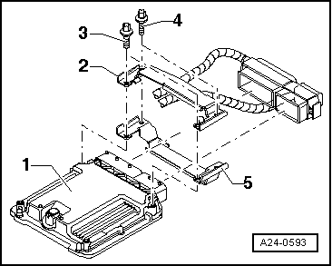
The engine control unit -1- is bolted to a protective casing -2 and 5-. To make it more difficult to unscrew the shear bolts -4- for locking plate -2-, their threads have been coated with locking fluid.
t
The metal housing has to be removed before the connectors can be unplugged from the engine control unit (e.g. to connect the test box or renew the engine control unit).
Removing
–
When renewing engine control unit, select diagnosis object „Replace engine control unit“ in „Guided Functions“. Use → Vehicle diagnostic tester.
–
Switch off ignition and remove ignition key.
–
Remove plenum chamber cover.
–
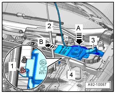
Slightly pull off rubber seal in front of nut -1- on plenum chamber cover.
–
Unhook wiring harness -2- from retainers -A-.
–
Remove nut -1-.
–
Pull filler neck -3- with filler pipe out of washer fluid reservoir and through opening in body.
–
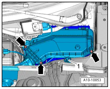
Unscrew bolts -arrows- and take off cover for electronics box.
–
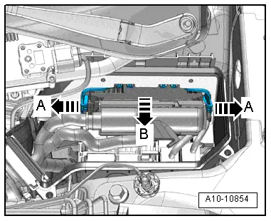
Release retainers -arrows A- and pull out engine control unit -J623--arrow B-.
Perform the following work steps if a protective housing is fitted:
To help prevent unauthorised access to the connectors on the engine control unit, the engine control unit -1- is bolted to a protective housing -5- by means of shear bolts -3 and 4- and a locking plate -2-.
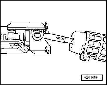
The threads of the two shear bolts -4- which are not screwed into the engine control unit are secured with locking fluid. To unscrew these two bolts, the threads must therefore be heated with the hot air blower.
The threads of the two shear bolts -3- which are screwed into the engine control unit are not secured with locking fluid. Do not apply heat to the threads in the control unit housing; this is not necessary and would cause overheating of the control unit.
–
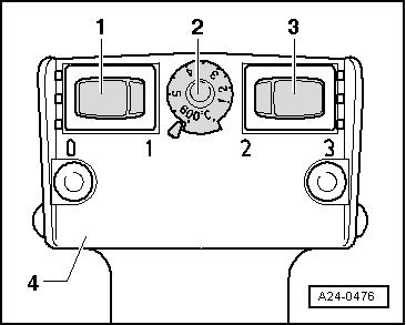
Select settings on hot air blower as shown in illustration, i.e. set temperature potentiometer -2- to maximum heat output and two-stage air flow switch -3- to position 3.
WARNING
The shear bolts and protective housing also become very hot when heating the threads of the locking mechanism. Take care to avoid burns. It is also important to ensure that only the thread is heated and none of the surrounding components if at all possible. These should be covered if necessary.
Switch on the hot air blower and heat the bolt for approximately 20 ... 30 seconds.
–
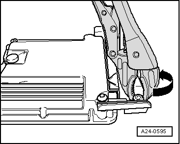
Unscrew shear bolts using suitable vice-grip pliers (see arrow in illustration).
–
The two shear bolts screwed into the engine control unit do not need to be heated. They should be removed without being heated.
–
Detach protective housing from control unit connectors.
–
Release connectors on engine control unit and unplug connectors.
–
Take out old engine control unit -J623- and install new engine control unit -J623-.
Installing
Installation is performed in the reverse sequence.
–
Make sure you fit protective housing (if fitted) back on engine control unit.
–
Clean threaded holes for shear bolts to remove any residue from locking fluid. This can be done using a thread tap.
–
Always use new shear bolts.
l
Tightening torque for bolts securing cover of electronics box: 3.5 Nm.
The procedure required after connecting the new engine control unit is described in the Guided Fault Finding or Guided Functions. Use → Vehicle diagnostic tester.
 Note
Note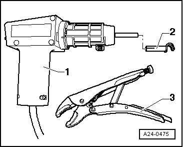
 WARNING