| t
| Set of cables -VAS 6606/7-1- and -VAS 6606/7-2- |

Note | t
| Always make sure that the cables are properly connected. |
| t
| Do not use damaged or worn tools and accessories. |
| t
| Observe operating instructions. |
| –
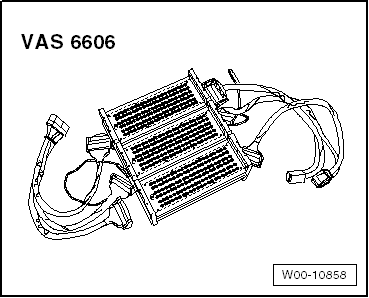
| Connect both cable sets -VAS 6606/7-1- and -VAS 6606/7-2- to the three isolator boxes -VAS 6606-. |
| –
| Use the following sheets: |
| t
| -VAS 6606/1-1- for isolator box, 198-pin -VAS 6606/1-1- |
| t
| -VAS 6606/2-1- for isolator box, 198-pin -VAS 6606/1-2- |
| t
| -VAS 6606/3-1- for isolator box, 198-pin -VAS 6606/1-3- |
Note | Make sure that all plug-in bridges are inserted completely in all isolator boxes. |
| –
| Connect earth strap to an isolator box and to an earth point on the vehicle. |
| –
| Connect engine control unit to cable set -VAS 6606/7-1-. |
| –
| Connect vehicle wiring harness to cable set -VAS 6606/7-2-. |
| The connection on the engine control unit consists of a large and a small connector. |
| The large connector has 105 pins and is assigned to the sheets for the isolator box marked „A 1 to A 105“. |
| The small connector has 91 pins and is assigned to the sheets for the isolator box marked „B 1 to B 91“. |
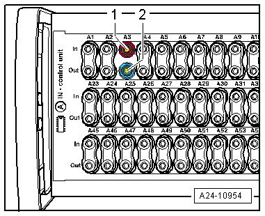
| When a push-in bridge is pulled out, the corresponding wiring connection is disconnected. |
Note | t
| The „In“ contact -1- (red socket) leads to the engine control unit. |
|
|
|