
5 Series E34 518g (M43) TOUR
13 80 ...
Function description for CNG (Compressed Natural Gas) vehicles
The CNG system
The gas system consists of a high-pressure section and a low-pressure section.
In order to store the maximum possible amount of gas in a restricted volume, it is compressed and filled and high
pressure into a tank. The compressed natural gas (C ompressed N atural G as) has a higher engergy to density ratio
than uncompressed natural gas. The high-pressure section comprises the filling, storage and transport of CNG from
the back of the vehicle to the front (enging compartment).
The high-pressure section is subject to the legislation on pressure vessels and the technical regulations governing gas.
It is equipped with special safety features.
To introduce the natural gas to the engine, all that is required his a slight pressure difference relative to inlet pipe
pressure. For this reason, CNG from the high-pressure section is relieved in to pressure regulators which increase its
pressure to slightly above nut in the inlet pipe. Gas is then distributed and induced into the engine through the metering
unit and the induction valves. The entire low-pressure section of the gas system is located in the engine compartment.
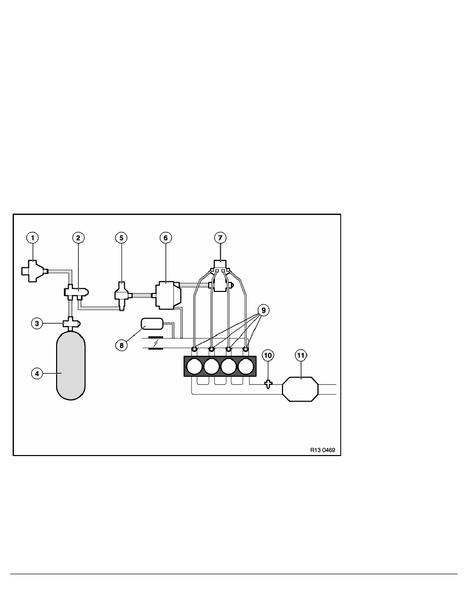
Schematic diagram of the CNG system
1
Filler connection
2
High-pressure non-return valve
3
Stop cock with gas density sensor, solder used and flow restrictor
4
CNG tank
5
High-pressure relief valve
6
Low-pressure regulator
7
Metering unit with low-pressure non-return valve
RA Function description for CNG (Compressed Natural Gas) vehicles
BMW AG - TIS
15.01.2013 13:12
Issue status (12/2007) Valid only until next DVD is issued
Copyright
Page - 1 -