
Crankshaft Position Sensor: Specifications (page 3 of 5)
- Make
- Buick
- Model
- Riviera
- Engine
- V6-231 3.8L VIN C SFI
- Year
- 1989
- Section
- Sensors and Switches - Powertrain Management › Sensors and Switches - Computers and Control Systems › Crankshaft Position Sensor
Crankshaft Position Sensor: Description and Operation
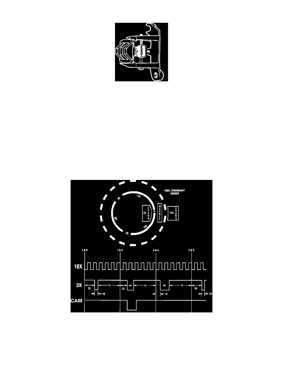
Dual Crankshaft Sensor
The C3I dual crank sensor, secured in an aluminum mounting bracket and bolted to the front left side of the engine timing cover, is partially behind the
crankshaft harmonic balancer. A 4-wire harness connector plugs into the sensor and connects it to the module. The dual crank sensor contains two
Hall-effect switches with one shared magnet mounted between them. The magnet and each Hall-Effect switch are separated by an air gap. The
Hall-Effect switch reacts like a solid-state switch, grounding a low current signal voltage when a magnetic field is present. When the magnetic field is
shielded from the switch by a piece of steel placed in the air gap between the switch and the magnet, the signal voltage is not grounded. If the piece of
steel is repeatedly moved in and out of the air gap, the signal voltage will appear to cycle. The piece of steel is two concentric interrupt rings mounted to
the rear of the crankshaft balancer. Each interrupter ring has blades and windows that, with crankshaft rotation, either block the magnetic field or let it
pass to one of the Hall-effect switches. The outer Hall-Effect switch is called the 18X crank sensor because this outer interrupt ring has 18 evenly spaced
blades and windows which are all the same width. The 18X crank sensor produces 18 "ON-OFF" pulses per crankshaft revolution. The Hall-effect switch
closest to the crankshaft is called the 3X crank sensor because it has 3 different unevenly spaced and different width size windows. The 3X crank sensor
produces 3 different length "ON-OFF" pulses per crankshaft revolution. When a 3X interrupter ring is between the magnet and the inner switch, the
magnetic field will cause the 3X Hall switch to ground the 3X signal voltage supplied from the C3I module. The 18X interrupt ring and Hall-effect
switch react similarly. The C3I module interprets the 18X and 3X pulse signals as an indication of crankshaft position, and must have both signals to fire
the correct ignition coil. The C3I module determines crank position for correct ignition coil sequencing by counting how many 18X signal transitions
occur during a 3X pulse.
Dual Crank Sensor Operation
Pinch or Ctrl + scroll to zoom. Double-tap to reset.
The same page in: Riviera V6-231 3.8L VIN C SFI (1989), Riviera V6-231 3.8L VIN C SFI (1989), Riviera V6-231 3.8L VIN C SFI (1989), Riviera V6-231 3.8L VIN C SFI (1989), Riviera V6-231 3.8L VIN C SFI (1989), Riviera V6-231 3.8L VIN C SFI (1989), Riviera V6-231 3.8L VIN C SFI (1989).
Parts & tools for this job For 1989 Buick Riviera 3.8L
- TOOLOBD2 scannerSearch: OBD2 scanner
- TOOLDigital multimeterSearch: automotive digital multimeter
- TOOLBack-probe test leadsSearch: back probe test leads
Links open Amazon search results in a new tab. As an Amazon Associate I earn from qualifying purchases.