
Riviera V6-3.8L SC VIN 1 (1995)
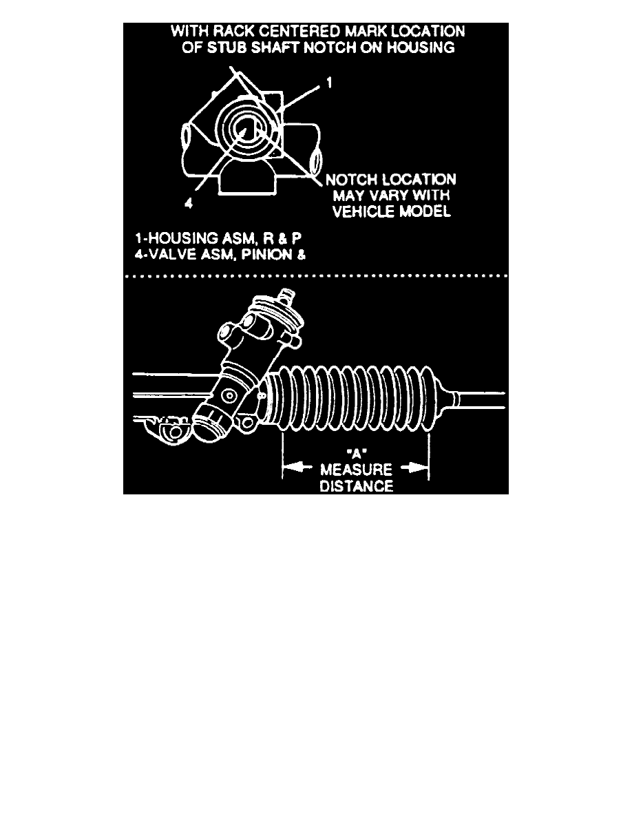
Fig. 22 Housing Reference Mark
REMOVAL
1. Remove rack and pinion steering assembly from vehicle.
2. Remove adjuster plug locknut from adjuster plug, Fig. 20.
3. Remove adjuster plug from housing, then adjuster spring and rack bearing.
4. Remove retaining ring from valve bore of housing then, the dust cover, Fig. 21.
5. Holding stub shaft, remove hex locknut from pinion and valve assembly. Stub shaft must be held to prevent damage to pinion teeth.
6. With rack centered, mark location of stub shaft notch on housing, then measure distance "A", as shown in Fig. 22.
7. Using a suitable press, press threaded end of pinion until the pinion and valve assembly is almost removed. Mark a second location of stub shaft
notch on housing. The second mark is used to position notch prior to reassembly.
8. Remove stub shaft dust seal, stub shaft seal, stub shaft bearing annulus assembly and pinion and valve assembly with retaining ring and valve body
rings attached.
9. If necessary, remove valve body rings from pinion and valve assembly, then clean ring grooves. Inspect pinion and valve assembly for broken
drive pin. If found, replace gear assembly.