
Catera V6-3.0L VIN R (1997)
20. Remove the LH/RH floor rear supply duct screws from the module.
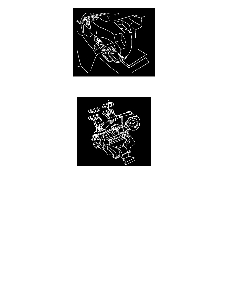
21. Remove the ducts from the module.
22. Reposition the wiring harness in order to allow the removal of the module.
23. Remove the module:
^
Carefully lift the upper vents from under the rubber seal.
^
Angle the module outward in order to remove.
INSTALLATION PROCEDURE
1. Install the air distribution module.
2. Position the wiring harness in order to facilitate the I/P carrier installation.
3. Install the RH/LH floor rear supply ducts.
4. Install the duct screws until fully seated and not stripped.
5. Install the module interior nut. Tighten the module interior nut to 4 Nm (35 lb. in).
6. Install the module engine compartment screws. Tighten the screws to 4 Nm (35 lb. in).
7. Install the following vacuum actuator components:
^
The electrical connections
^
The hoses
8. Position the I/P support brace at the I/P and at the transmission well.
9. Install the I/P support brace bolts at the I/P and at the transmission well. Tighten the bolts to 22 Nm (16 lb. ft).
10. Install the heater core inlet and outlet pipes:
^
Use new O-rings.
^
Lightly lubricate the O-rings with coolant.
11. Install the heater core inlet and outlet pipe retaining bracket screw. Tighten the screw to 5 Nm (44 lb. in).
12. Install the heater core pipe bracket.
13. Install the heater core pipe bracket screw until fully seated and not stripped.
14. Connect the electrically operated actuator connectors.
15. Connect the vacuum line connection at the cowl.
16. Install the I/P carrier.
17. Install the steering column.
18. Install the evaporator line extension bolt to the cowl. Tighten the bolt to 20 Nm (15 lb. ft).