
Catera V6-3.0L VIN R (1997)
Relay Rod: Service and Repair
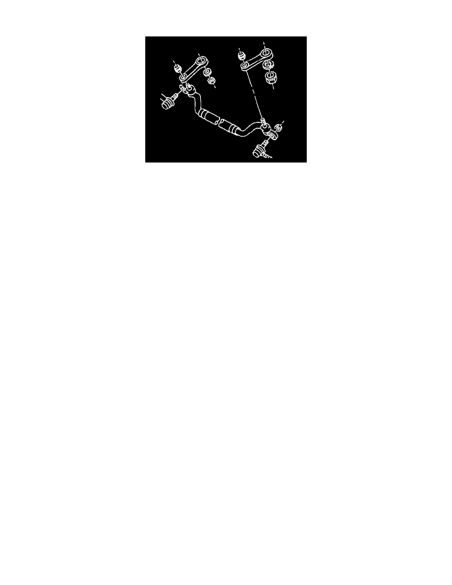
REMOVAL PROCEDURE
^
Tools Required:
-
J 6627-A Tie Rod / Wheel Stud Puller
-
J 42089 Linkage Installer
-
J 42400 Relay Rod Removal Tool
-
Or Equivalents
NOTICE: Do not attempt to disconnect a steering linkage joint by driving a wedge between the joint and the attached part. Seal damage may result
which will cause premature failure of the joint.
CAUTION: To help avoid personal injury when a vehicle is on a hoist, provide additional support for the vehicle at the opposite end from
which components are being removed. This will reduce the possibility of the vehicle falling off the hoist.
1. Raise and support the vehicle.
2. Remove the inner tie rods from the relay rod.
3. Remove the relay rod ball stud nut from the pitman arm.
4. Use the J 42400 to remove the relay rod ball stud from the pitman arm.
5. Remove the relay rod ball stud nut from the idler arm.
6. Use the J 42400 to remove the relay rod ball stud from the idler arm.
INSTALLATION PROCEDURE
1. Install the relay rod to the idler arm.
2. Install the J 42089 to the relay rod ball stud.
^
Tighten the J 42089 to 30 Nm (22 ft. lbs.) to allow the ball stud taper to seat.
NOTICE: Use the correct fastener in the correct location. Replacement fasteners must be the correct part number for that application.
Fasteners requiring replacement or fasteners requiring the use of thread locking compound or sealant are identified in the service procedure.
Do not use paints, lubricants, or corrosion inhibitors on fasteners or fastener joint surfaces unless specified. These coatings affect fastener
torque and joint clamping force and may damage the fastener. Use the correct tightening sequence and specifications when installing fasteners
in order to avoid damage to parts and systems.
3. Remove the J 42089 from the relay rod ball stud.
Important: Use a new self-locking tie rod ball stud nut.
4. Install the relay rod ball stud-to-idler arm nut.
^
Tighten the relay rod ball stud-to-idler arm nut to 60 Nm (44 ft. lbs.).
5. Install the relay rod to the pitman arm.
6. Install the J 42089 to the relay rod ball stud.
^
Tighten the J 42089 to 30 Nm (22 ft. lbs.) to allow the ball stud taper to seat.
7. Remove the J 42089 from the relay rod ball stud.
Important: Use a new self-locking tie rod ball stud nut.
8. Install the relay ball stud-to-pitman arm nut.
^
Tighten the relay rod ball stud-to-pitman arm nut to 60 Nm (44 ft. lbs.).
9. Install the inner tie rods to the relay rod.