
DeVille V8-4.9L VIN B (1995)
To navigate through these "Cell" references start at the vehicle level and go to: Diagrams / Electrical Diagrams - for a complete list of the diagrams
available for the vehicle. Choose the system you are working on and view those diagrams.
Note: If unsure of the system - try utilizing the search feature. Type a component in the search feature that belongs to the system and when the
results are displayed note the path displayed. This will show the system the component belongs in.
Commonly Used Abbreviations
A/C
Air Conditioning
CCM
Central Control Module
CKT
Circuit
CONN
Connector
EBCM
Electronic Brake Control Module
EBTCM
Electronic Brake and Traction Control Module
ECM
Engine Control Module
HARN
Harness
I/P
Instrument Panel
LH
Left Hand
PCM
Powertrain Control Module
RH
Right Hand
TERM
Terminal
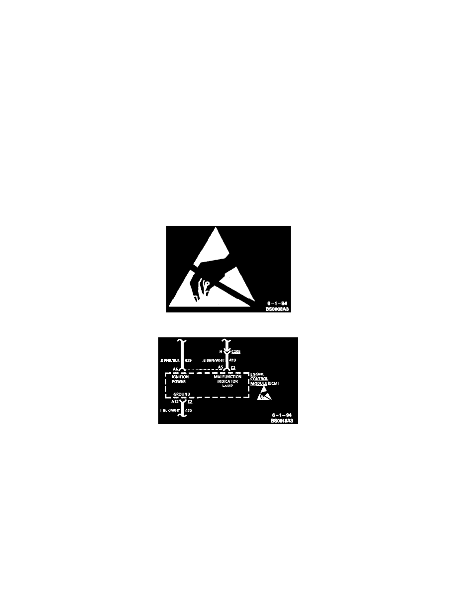
Electrostatic Discharge (ESD Sensitive Devices)
All Electrostatic Discharge (ESD) sensitive components are Solid State and the following information applies to them.
ESD Symbol
Typical Schematic
The ESD symbol is used on schematics to indicate which components are ESD sensitive. When handling any electronic part, the service technician
should follow the guidelines below to reduce any possible electrostatic charge build-up on the service technician's body and inadvertent discharge to the
electronic part. If it is not known whether or not a component is ESD sensitive, assume it is susceptible.
Handling Procedures
1. Always touch a known good ground before handling the part. This should be repeated while handling the pan and more frequently after sliding
across a seat, sitting down from a standing position or walking a distance.
2. Avoid touching electrical terminals of the part, unless so instructed by a written diagnostic procedure.
3. When using a voltmeter, be sure to connect the ground lead first.
4. Do not remove a part from its protective package until it is time to install the part.
5. Before removing the part from its package, ground the package to a known good ground on the vehicle.
Measuring Procedures
The circuits shown within the boxes are greatly simplified. Do not troubleshoot by measuring resistance at any terminal of these devices unless so