
Escalade V8-5.7L VIN R (2000)
Diagnostic Chart (Part 2 Of 2)
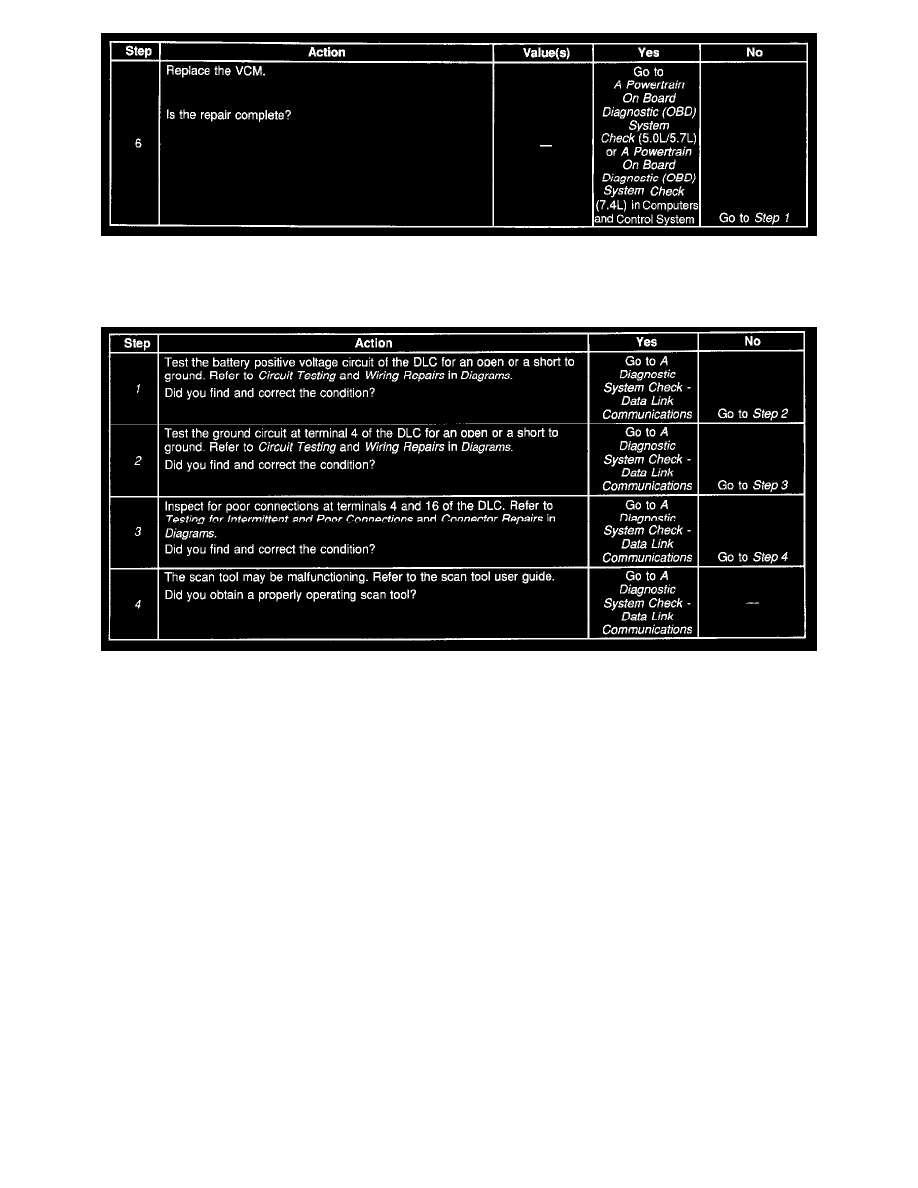
Scan Tool Does Not Power Up
Diagnostic Chart
CIRCUIT DESCRIPTION
The data link connector (DLC) provides operating power for the scan tool at terminal 16 (battery positive voltage) and at terminal 4 (ground). The
DLC provides the class 2 serial data signal at terminal 2 and signal ground at terminal 5. The scan tool will power up with the ignition off. Many
modules, however, will not communicate unless the body control module (BCM) detects that the ignition is on and sends the appropriate power mode
message.
TEST DESCRIPTION
The number(s) below refer to the step number(s) on the diagnostic table.
1. This step checks the power portion of the circuit.
2. This step checks the ground portion of the circuit.
3. This step checks for poor connections and properly seated terminals.
4. This step indicates a malfunctioning scan tool and instructs the technician to obtain a properly operating scan tool.