
Fleetwood V8-350 5.7L VIN P MFI (1995)
Engine Control Module: Pinout Values and Diagnostic Parameters
Read This Before Checking Voltages
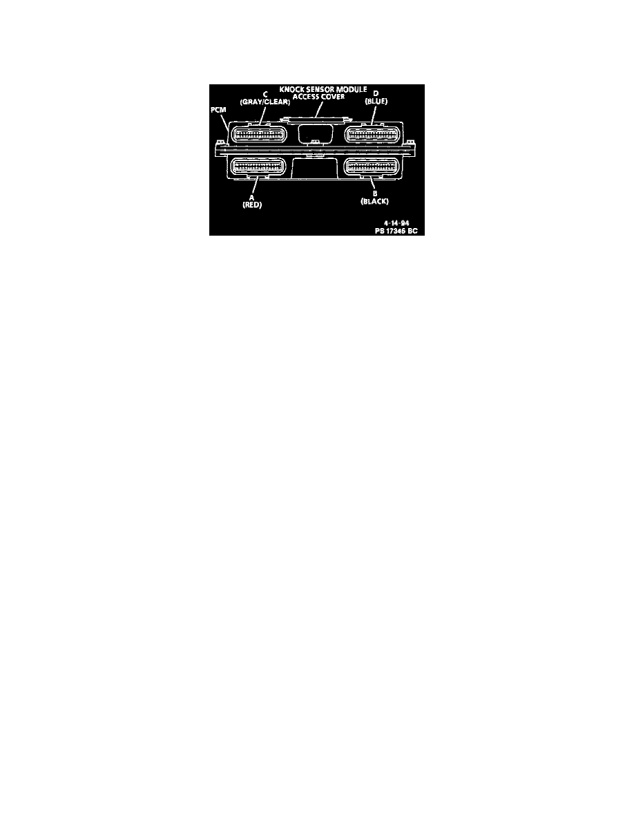
PCM Connectors
BACKPROBING CONNECTORS
Do Not backprobe Powertrain Control Module (PCM) connectors! The connectors are sealed for operation in an underhood environment.
Backprobing may damage the seal which could eventually cause the connector to fail due to corrosion.
BEFORE CHECKING VOLTAGES
The following conditions, listed below, must be met before checking the typical connector pinout voltages found in the charts under this heading:
Key ON
^
DVOM negative (black) lead connected to a known good ground.
^
Scan tool NOT installed.
^
All accessories "OFF."
^
Battery fully charged.
Engine Running
^
All conditions listed above.
^
Engine at normal operating temperature.
^
Engine at idle, closed throttle and operating in "Closed Loop."
^
In park or neutral.
TEST EQUIPMENT
The PCM pinout voltage charts may be used with the J 39700-A breakout box in conjunction with J 39700-110 and J 39700-140 cables and high
impedance digital multimeter J 39200 to obtain voltage present for each circuit listed. Install the breakout box between the PCM connectors and the
PCM. The breakout box PIN numbers correspond with the PCM connector PIN numbers. Voltage may vary slightly, but should be very close.
Certain exceptions are called out in the chart legends accompanying each chart.
PCM Connector A (Red)