
Fleetwood V8-368 6.0L VIN 9 FI (1982)
Radiator Cooling Fan Control Module: Testing and Inspection
*** UPDATED BY TSB 87-130, DATED JULY 87 ***
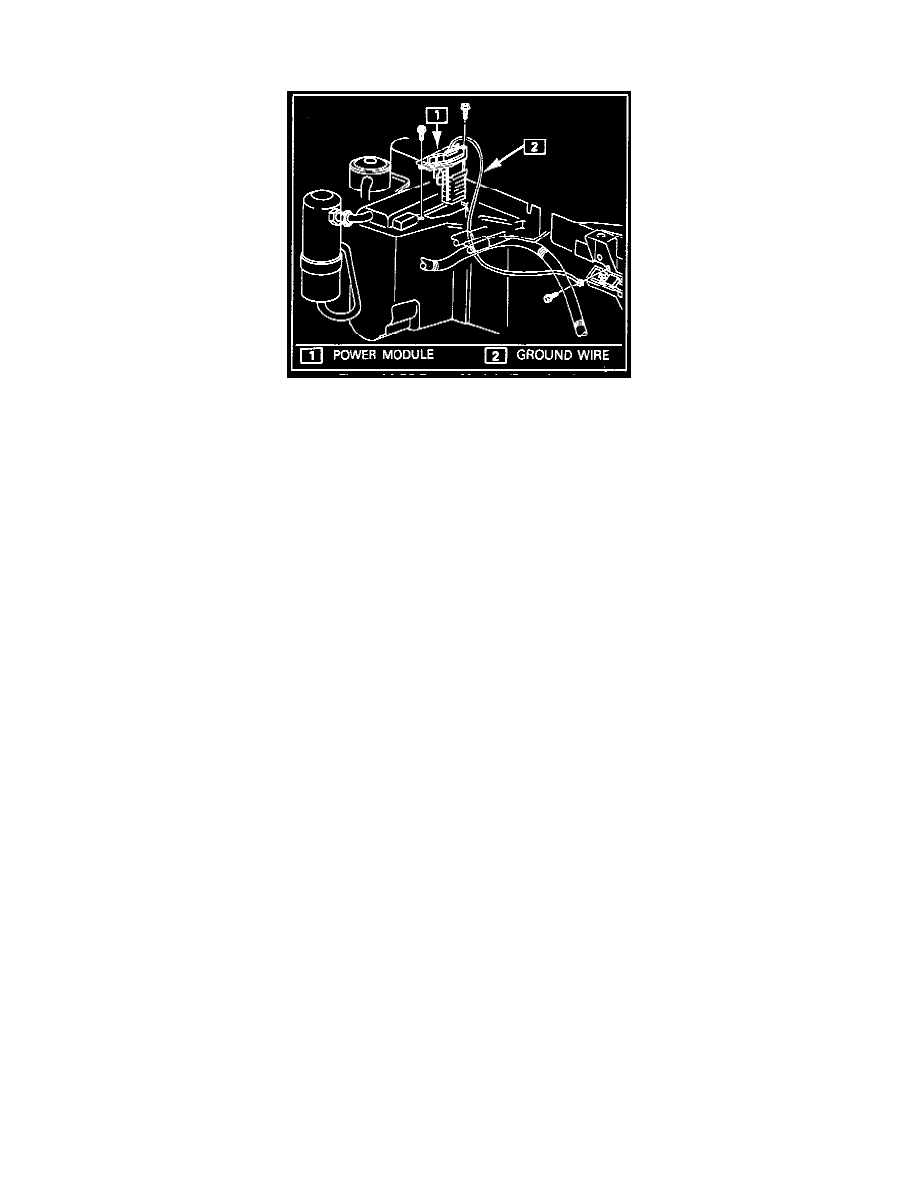
Typical Power Module Location Under Hood.
SYMPTOMS:
Some vehicles may experience one of the following conditions:
-
Compressor clutch operates in off and/or econ setting
-
Compressor clutch does not operate
-
Compressor clutch cycles rapidly
-
Blower motor does not operate
-
Blower motor operates in off setting or with key off. NOTE: Low blower operation in the off setting is normal on 1980 Eldorados and Sevilles
equipped with ECC
-
Power module fails repeatedly
The above conditions may be caused by an inoperative power module. Before replacing the power module for the conditions listed above, the blower
motor and compressor clutch circuits should be checked using the procedures given below to determine if either may have contributed to the power
module failure.
TEST PROCEDURE:
The following procedure should be used before replacing the power module to check the blower motor and compressor clutch circuits on the cars
listed above.
To check the compressor clutch and circuit:
1. Disconnect the power module 6-way connector.
2. Jumper 12 volts to circuit 204 (pin C on 1980-81 E and K cars, pin A on all other cars) through a 5 amp in-line fuse. If the fuse does not blow
within two minutes, the compressor clutch did not cause the power module failure (proceed to "Check the blower motor circuit").
3. If the 5 amp fuse blows, remove the compressor clutch coil connector and check the clutch diode using the diode check setting on a DVOM. If the
diode checks bad, replace the diode.
4. Check voltage to ground and resistance to ground on circuit 204 with the power module and compressor clutch coil disconnected and the ignition
in the run position using a DVOM. A voltage reading over .1 volt indicates there is a short to voltage on circuit 204, which should be repaired. If a
short to ground is found on circuit 204, this should be repaired. If circuit 204 checks ok, replace the compressor clutch coil.
To check the blower motor circuit:
1. Disconnect the single wire connector (blower motor control circuit 918) from the power module. Select 60° AUTO ECC setting.
2. Connect an ammeter with greater than 25 amp capacity between the single wire connector and ground. This will turn the blower on full and give a
blower motor draw reading. If an ammeter with 25 amp capacity is unavailable, substitute a 20 amp inline fuse for the ammeter and use heavy gage
jumpers from circuit 918 to the in-line fuse and from the in-line fuse to ground.
3a. If an ammeter is used: