
Fleetwood V8-368 6.0L VIN 9 FI (1982)
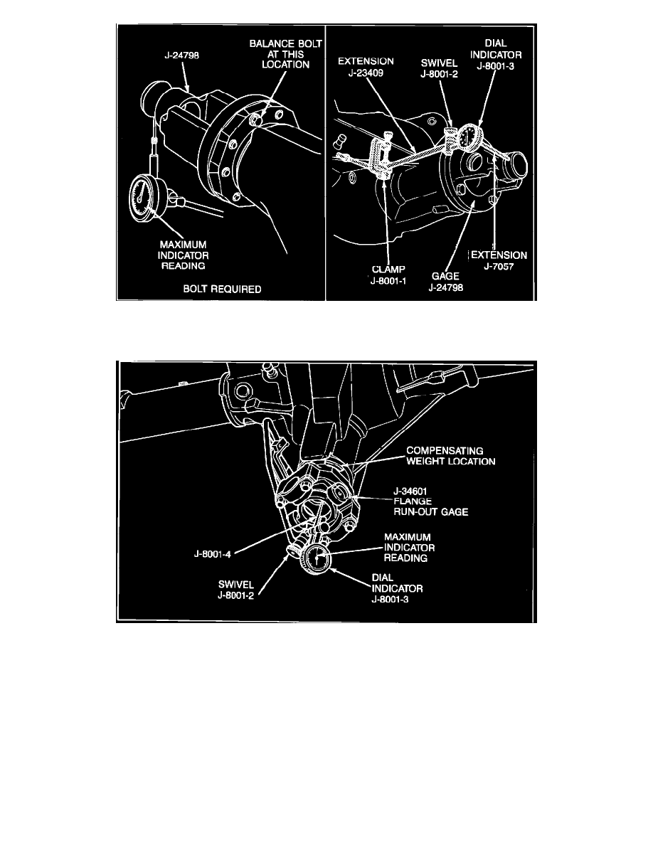
FIGURE 2 - CHECKING PINION FLANGE RUNOUT
IV. Check pinion flange runout, refer to Section A for 7-1/2" axle assembly (Figure 1) and Section B for 8-3/4" (Figure 2).
FIGURE 1 - CHECKING PINION FLANGE RUNOUT
A.
Check pinion flange runout on a 7-1/2" axle assembly as follows:
1.
Install pinion flange runout gage J-34601 using the same bolts and straps as used to install the propeller shaft, refer to Figure 1.
2.
Rotate the pinion flange one complete revolution, and zero indicator at the point of the lowest reading.
3.
Rotate the pinion flange until the dial indicator shows maximum reading.
4.
If runout exceeds .006" Total Indicator Runout (TIR), the pinion flange should be indexed 180~ in relation to the pinion; and runout
should be checked again. If the runout is still in excess of .006", replace the pinion flange (and repeat step A).
5.
If the pinion flange was re-indexed in step 4 and the TIR is .005" or less, remove the compensating weight from the front of the pinion
flange slinger, refer to Figure