
Seville STS V8-4.6L VIN 9 (1998)
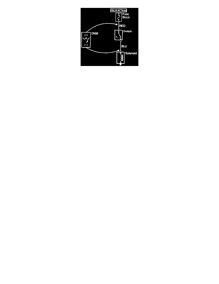
Testing For Voltage Drop
This test checks for voltage being lost along a wire or through a connection or switch.
1. Connect the positive lead of a DMM to the end of the wire or to one side of the connection, or to the switch whichever is closer to the battery.
2. Connect the negative lead to the other end of the wire or to the other side of the connection, or switch.
3. Operate the circuit.
4. The DMM will show the difference in voltage between the two points.
Using Fused Jumper Wires
IMPORTANT: A fused jumper may not protect solid state components from being damaged.
The J 36169-A fused jumper includes small clamp connectors that provide adaptation to most connectors without damage. This fused jumper wire is
supplied with a 20 A fuse which may not be suitable for some circuits. Do not use a fuse with a higher rating than the fuse that protects the circuit being
tested.
Test Light
A test light can simply and quickly check a circuit for voltage.
The J 34142-B test light is comprised of a 12 volt light bulb with an attached pair of leads. To properly operate this tool use the following procedure.
1. Attach one lead to ground.
2. Touch the other lead to various points along the circuit where voltage should be present.
3. When the bulb illuminates, there is voltage at the point being tested.
Digital Multimeter
NOTE: Refer to DMM Test Probe Notice in Cautions and Notices.
IMPORTANT: Circuits which include any solid state control modules, such as the PCM, should be tested only with a 10 megohm or higher impedance
J 39200 digital multi meter.
The J 39200 Instruction Manual is a good source of information and should be read thoroughly upon receipt of the DMM as well as kept on hand for
reference during new procedures.
A DMM should be used instead of a test light to check for voltage. While a test light shows whether voltage is present, a DMM indicates how much
voltage is present.
When testing for voltage or continuity at the connection, it is not necessary to separate the two halves of the connector. Unless testing a Weather
Pack(rear), a Metri Pack(rear) or other sealed system, always probe the connector from the back. Always check both sides of the connector. An
accumulation of dirt and corrosion between contact surfaces is sometimes a cause of electrical problems.
The ohmmeter function on a DMM shows how much resistance exists between two points along a circuit. Low resistance in a circuit means good
continuity.
IMPORTANT: Disconnect the battery when measuring resistance with a DMM. This prevents incorrect readings.
DMMs apply such a small voltage to measure resistance that the presence of voltages can upset a resistance reading.
Diodes and solid state components in a circuit can cause a DMM to display a false reading. To find-out if a component is affecting a measurement take a
reading once, then reverse the leads and take a second reading. If the readings differ the solid state component is affecting the measurement. Following
are examples of the various methods of connecting the DMM to the circuit to be checked:
^
Backprobe both ends of the connector and either hold the leads in place while manipulating the connector or tape the leads to the harness for
continuous monitoring while you perform other operations or test driving.
^
Disconnect the harness at both ends of the suspected circuit where it connects either to a component or to other harnesses.