
SRX AWD V6-3.0L (2010)
Circuit/System Description
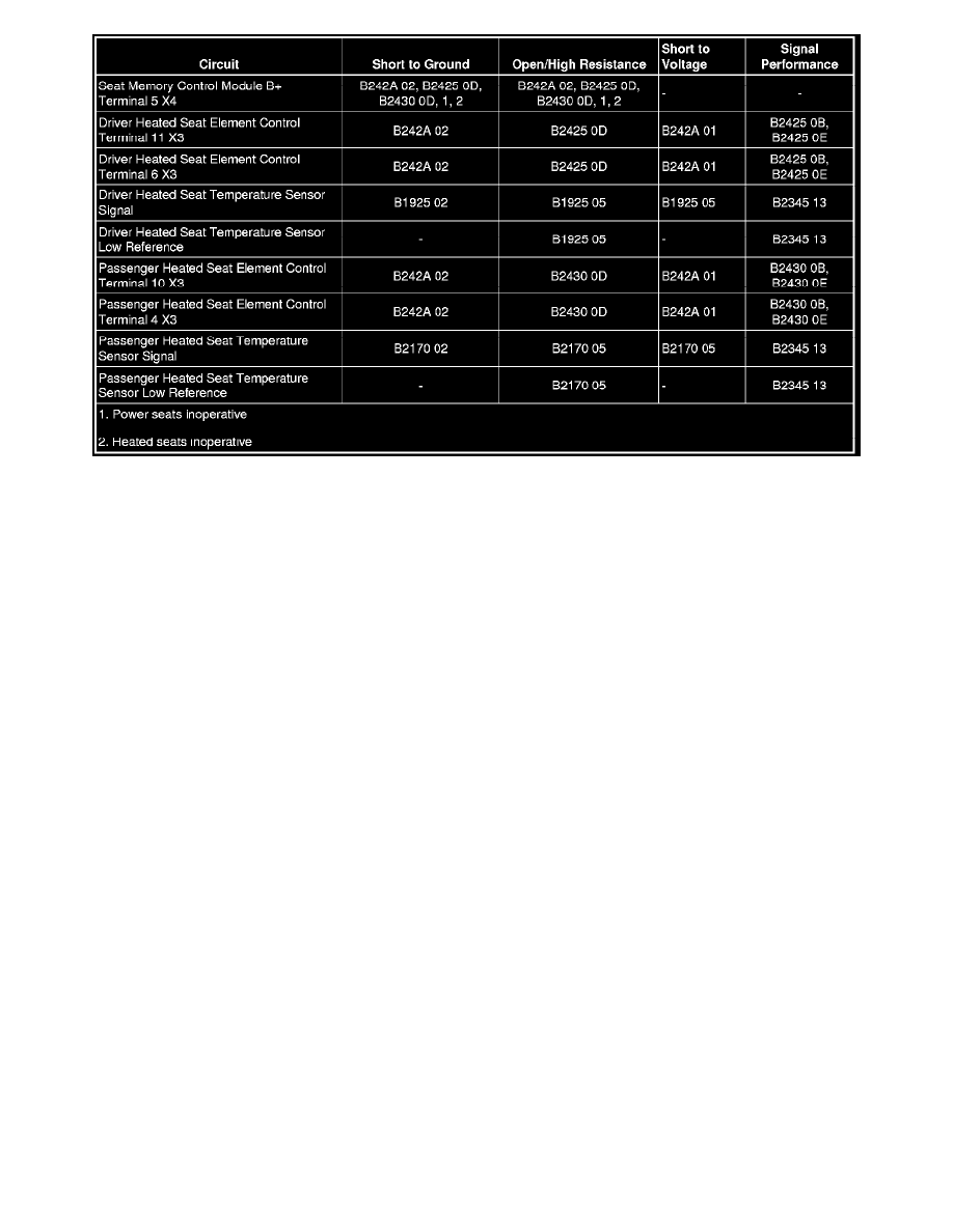
The driver and front passenger heated seats are controlled by separate heated seat switches that are located in the radio/HVAC controls. When a heated
seat switch is pressed, a serial data message is sent from the radio/HVAC controls to the HVAC control module indicating the heated seat command. The
HVAC control module serves as a gateway to transmit the message to the seat memory control module via the serial data line. In response to this
message, the seat memory control module applies battery voltage through the element supply voltage circuit to the appropriate seat heating elements. The
seat memory control module then sends a serial data message back to the HVAC control module to gateway the information to the radio/HVAC controls
to either illuminate or turn off the appropriate temperature indicator.
Reference Information
Schematic Reference
Heated/Cooled Seat Schematics (See: Diagrams/Electrical Diagrams)
Connector End View Reference
Component Connector End Views (See: Diagrams/Connector Views/Connector End Views By Name)
Description and Operation
Heated/Vented Seat Description and Operation (See: Description and Operation/Heated/Vented Seat)
Electrical Information Reference
*
Circuit Testing (See: Testing and Inspection/Component Tests and General Diagnostics/General Electrical Diagnostic Procedures/Circuit
Testing/Circuit Testing)
*
Connector Repairs (See: Testing and Inspection/Component Tests and General Diagnostics/General Electrical Diagnostic Procedures/Connector
Repairs/Connector Repairs)
*
Testing for Intermittent Conditions and Poor Connections (See: Testing and Inspection/Component Tests and General Diagnostics/General
Electrical Diagnostic Procedures/Circuit Testing/Testing for Intermittent Conditions and Poor Connections)
*
Wiring Repairs (See: Testing and Inspection/Component Tests and General Diagnostics/General Electrical Diagnostic Procedures/Wiring
Repairs/Wiring Repairs)
Scan Tool Reference
Control Module References (See: Testing and Inspection/Programming and Relearning) for scan tool information
Circuit/System Testing
1. Ignition OFF, disconnect the X4 harness connector at the K40 seat memory control module.
2. Ignition ON, verify that a test lamp illuminates between the B+ circuit terminal 5 and ground.
‹› If the test lamp does not illuminate, test the B+ circuit for a short to ground or an open/high resistance.