
STS V8-4.6L VIN A (2005)
Variable Valve Timing Actuator: Description and Operation
CAMSHAFT ACTUATOR SYSTEM DESCRIPTION
The camshaft position (CMP) actuator system is used for a variety of engine performance enhancements. The CMP actuator system accomplishes this by
controlling the amount of intake and exhaust valve overlap. These enhancements include the following:
-
Lower emission output through exhaust gas recirculation (EGR) control
-
A wider engine torque range
-
Improved gas mileage
-
Improved engine idle stability
The CMP actuator system is comprised of the following components:
-
Four CMP actuator solenoids
-
Four oil control valves
-
Four vane style CMP actuators
-
Four CMP sensors
The CMP actuator system requires a very complex electrical signal from the engine control module (ECM) in order to control the position of the CMP
actuators. The electrical signal requires use of an un-fixed pulse width modulation (PWM) signal as well as 2 different operating frequencies of 150 and
500 Hz. Changes in the PWM can happen every 100 milliseconds and thus makes it difficult to measure the correct PWM or frequency with a DMM
during CMP actuator control. At idle, the ECM commands a consistent 7 percent duty cycle at 150 Hz. The ECM uses this signal in order to sense
certain circuit failures.
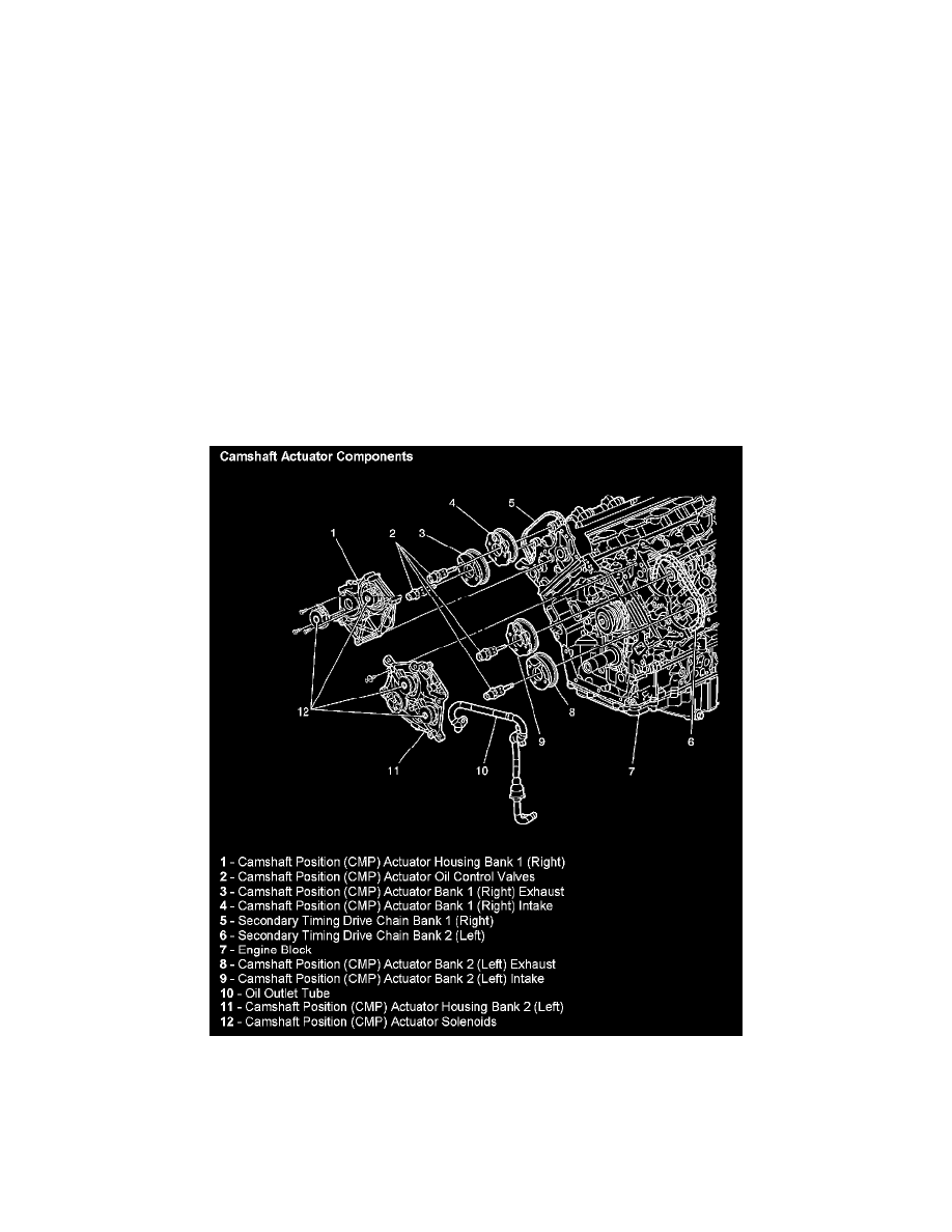
Camshaft Actuator Components
The CMP actuator solenoids, or electromagnets, are located on the front of the engine and are mounted to their corresponding bank CMP actuator
housing.
The oil control valves are threaded, and attach the CMP actuators to the front of the camshafts. The oil control valve meters the oil flow to the CMP
actuator through the advancing and retarding oil ports. With no command fro the ECM, all of the oil is ported to the advancing chambers of the exhaust