
STS RWD V8-4.6L (2007)
Variable Valve Timing Actuator: Description and Operation
Camshaft Actuator System Description
The camshaft position (CMP) actuator system is used for a variety of engine performance enhancements. The CMP actuator system accomplishes this by
controlling the amount of intake and exhaust valve overlap. These enhancements include the following:
* Lower emission output through exhaust gas recirculation (EGR) control
* A wider engine torque range
* Improved gas mileage
* Improved engine idle stability
The CMP actuator system is comprised of the following components:
* Four CMP actuator solenoids
* Four oil control valves
* Four vane style CMP actuators
* Four CMP sensors
The CMP actuator system requires a very complex electrical signal from the engine control module (ECM) in order to control the position of the CMP
actuators. The electrical signal requires use of an un-fixed pulse width modulation (PWM) signal as well as 2 different operating frequencies of 150 and
500 Hz. Changes in the PWM can happen every 100 milliseconds and thus makes it difficult to measure the correct PWM or frequency with a DMM
during CMP actuator control. At idle, the ECM commands a consistent 7 percent duty cycle at 150 Hz. The ECM uses this signal in order to sense
certain circuit failures.
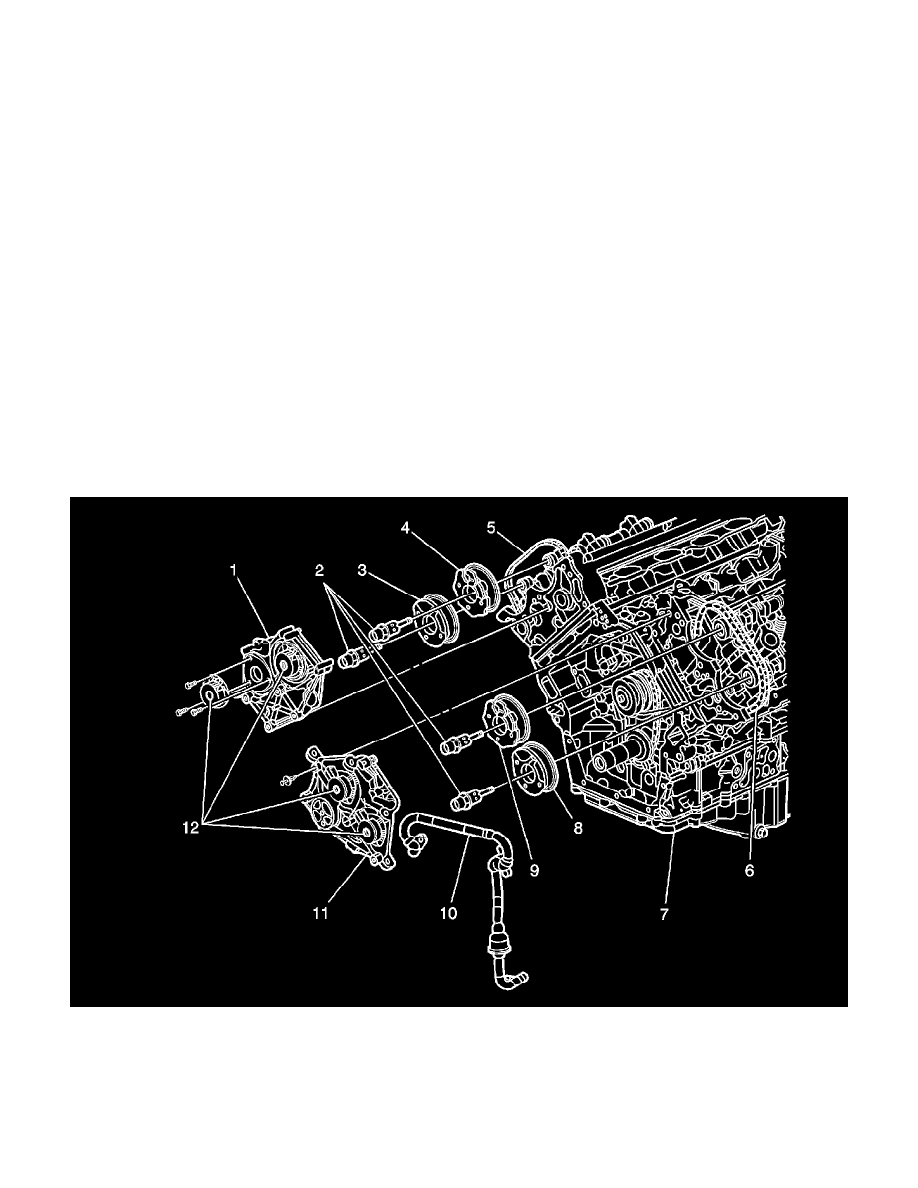
Camshaft Actuator Components
1 - Camshaft Position (CMP) Actuator Housing Bank 1 (Right)
2 - Camshaft Position (CMP) Actuator Oil Control Valves
3 - Camshaft Position (CMP) Actuator Bank 1 (Right) Exhaust
4 - Camshaft Position (CMP) Actuator Bank 1 (Right) Intake
5 - Secondary Timing Drive Chain Bank 1 (Right)
6 - Secondary Timing Drive Chain Bank 2 (Left)
7 - Engine Block