
Camaro V8-6.2L (2010)
Alignment: Service and Repair
Rear Camber Adjustment
Rear Camber Adjustment
Danger: To avoid any vehicle damage, serious personal injury or death when major components are removed from the vehicle and the
vehicle is supported by a hoist, support the vehicle with jack stands at the opposite end from which the components are being removed
and strap the vehicle to the hoist.
Warning: Refer to Safety Glasses Warning (See: Service Precautions/Technician Safety Information/Safety Glasses Warning).
1. Before performing any adjustment affecting the wheel alignment, refer to Wheel Alignment Measurement (See: Wheel Alignment Measurement).
2. Raise and support the vehicle. Refer to Lifting and Jacking the Vehicle (See: Wheels and Tires/Vehicle Lifting/Service and Repair).
Note:
*
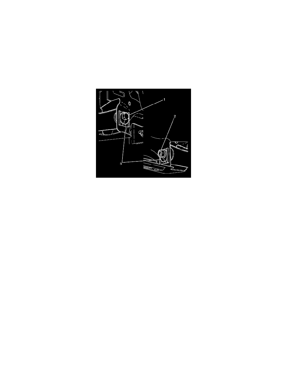
The lower control arm to the subframe retaining bolt (1) and nut (2) eccentric washers (3) are used to adjust rear suspension camber.
*
Nuts with micro-encapsulated thread sealant must be discarded after removal.
3. Remove the lower control arm to the subframe retaining nut (2). Discard the nut.
Note: The lower control arm to the subframe retaining nut (2) is not to be fully tightened until after the rear suspension camber has been adjusted.
4. Install NEW lower control arm to the subframe retaining nut (2).
Do not fully tighten at this stage.
5. Remove the safety stands.
6. Lower the vehicle to the ground.
Note: Before checking and adjusting any wheel alignment angles bounce the vehicle to settle the suspension at normal ride height.
7. Bounce the vehicle several times to settle the suspension.
8. Determine the actual rear suspension camber angle.
9. Adjust the rear suspension camber to specification by turning the lower control arm to subframe retaining bolt (1). For rear suspension camber
specifications, refer to Wheel Alignment Specifications (See: Specifications/Wheel Alignment Specifications).
Caution: Refer to Fastener Caution (See: Service Precautions/Vehicle Damage Warnings/Fastener Caution).
Note:
*
The weight of the vehicle must be on a level surface such as an alignment rack and on all four wheels before fully tightening the bolts and nuts
that have been partially tightened. Failure to comply with this requirement may adversely affect the ride and handling characteristics of the
vehicle.
*
Do not allow the lower control arm to subframe retaining bolt (1) to turn while tightening.
10. Tighten the lower control arm to subframe retaining bolt (1) and nut (2) to 175 Nm (129 lb ft).
11. Verify that camber is still within specifications. Refer to Wheel Alignment Specifications (See: Specifications/Wheel Alignment Specifications).
12. If further adjustment is required, adjust as necessary.