
EL Camino V8-350 5.7L DSL (1982)
8. Remove injection pump top cover, then remove screws from cover.
CAUTION: When the injection pump top cover is removed, extreme care must be taken to keep foreign materials out of the pump. If any objects
are dropped in the injection pump, they must be removed before the engine is started to prevent engine or injection pump damage.
9. Note position of metering valve spring over top of guide stud. This position must be duplicated exactly during reassembly.
10. Remove guide stud and washer, Fig. 63. Note part location prior to removal.
11. Rotate min-max governor assembly upwards to provide clearance, then remove from throttle shaft, Fig. 76.
12. Remove throttle shaft assembly and examine shaft for unusual wear or damage. Replace if necessary. When removing throttle shaft assembly, it
may be necessary to loosen the injection pump mounting nuts and rotate pump slightly to provide clearance for shaft removal.
13. Examine pump housing bushings for unusual wear or damage. If wear is evident, the pump should be removed and sent to manufacturer for
repairs.
14. Remove throttle shaft seals. Do not attempt to cut seals to remove, as nicks in the seat will cause fuel leakage.
15. Install replacement shaft seals taking care not to cut seals on shaft edges. Apply chassis lube lightly to the seals.
16. Slide the throttle shaft assembly carefully into the pump body to the point the min-max governor assembly will slide back onto the throttle shaft
assembly, Fig. 76.
17. Rotate the min-max governor assembly downward into the pump body, then while holding in position, slide the throttle shaft and governor
assembly into position.
18. Install new mylar washer, throttle shaft advance cam (do not tighten screw at this time) and throttle shaft drive pin. Align the throttle shaft advance
cam so tool J-29601 can be reinstalled over the throttle shaft, pin in the slots and the spring clip over the advance cam, Fig. 75. Insert a .005 inch
feeler gauge between the mylar washer on the throttle shaft and the pump housing. Squeeze the cam and throttle shaft together and tighten the cam
screw. Torque to 30 inch lbs. Secure with suitable locking compound.
19. Install guide stud with new washer, Fig. 63. Ensure the metering valve spring upper extension rides on top of the guide stud. Torque guide stud to
85 inch lbs. Do not overtorque.
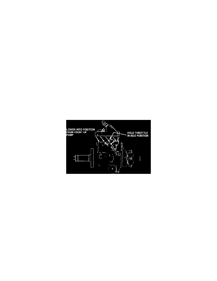
20. Hold throttle in idle position.
21. Install new pump cover seal. Ensure the securing screws are not in the cover and position the cover approximately 1/4 inch forward and 1/8 inch
above the pump.
Fig. 77 Installing injection pump cover
22. Move cover rearward and downward into proper position, using caution not to cut the seal, then install pump cover screws, Fig. 77. Torque screws
to 35 inch lbs. Use caution not to drop and lose flat washer and internal lock washer with each screw. Flat washers must be against pump
cover.
23. On 1980 models, install vacuum regulator valve. On 1981 and 1983---84 models, install vacuum regulator valve aligning marks made previously.
24. Connect battery ground cables.
25. Turn ignition to "Run" position. Touch pink solenoid wire to the injection pump solenoid terminal. A clicking noise should be heard indicating the
fuel solenoid is operating. If clicking noise is heard, proceed to step 28. If no clicking noise is heard, the solenoid linkage may be jammed in a
wide open position and the engine must not be started. Proceed to step 26.
26. Remove injection pump top cover, then ground the solenoid lead opposite the hot lead and connect the pink wire. With ignition switch in the
"Run" position, the solenoid should move the linkage. If not, replace the solenoid. The minimum voltage across the solenoid terminals must be
12 volts.
27. Reinstall cover and repeat step 25.
28. Install throttle cable bracket and throttle rod, then install throttle cable and return spring. Connect solenoid wire and on 1981 and 1983---84
models housing pressure cold advance (HPCA) wire.
29. Install fuel return line. Ensure the timing mark on the pump is aligned with the adapter timing mark. Also ensure the injection pump retaining bolts
are tight.
30. Start engine and check for leaks. If engine roughness is observed, it may be due to air in the pump. To purge air, let engine idle for several
minutes. It may be necessary to shut engine down for several minutes to allow air bubbles to rise to top of pump where they will be purged.
31. Remove intake manifold screens, then reinstall air crossover and air cleaner.