
Equinox AWD V6-3.4L (2008)
15. Remove the rear wheel drive shafts. Refer to Rear Wheel Drive Shaft Replacement (See: Transmission and Drivetrain/Drive Axles, Bearings and
Joints/Axle Shaft Assembly/Service and Repair/Rear Wheel Drive Shaft Replacement) .
16. Remove the rear differential. Refer to Differential Replacement (See: Transmission and Drivetrain/Differential Assembly/Service and
Repair/Removal and Replacement/Differential Replacement) .
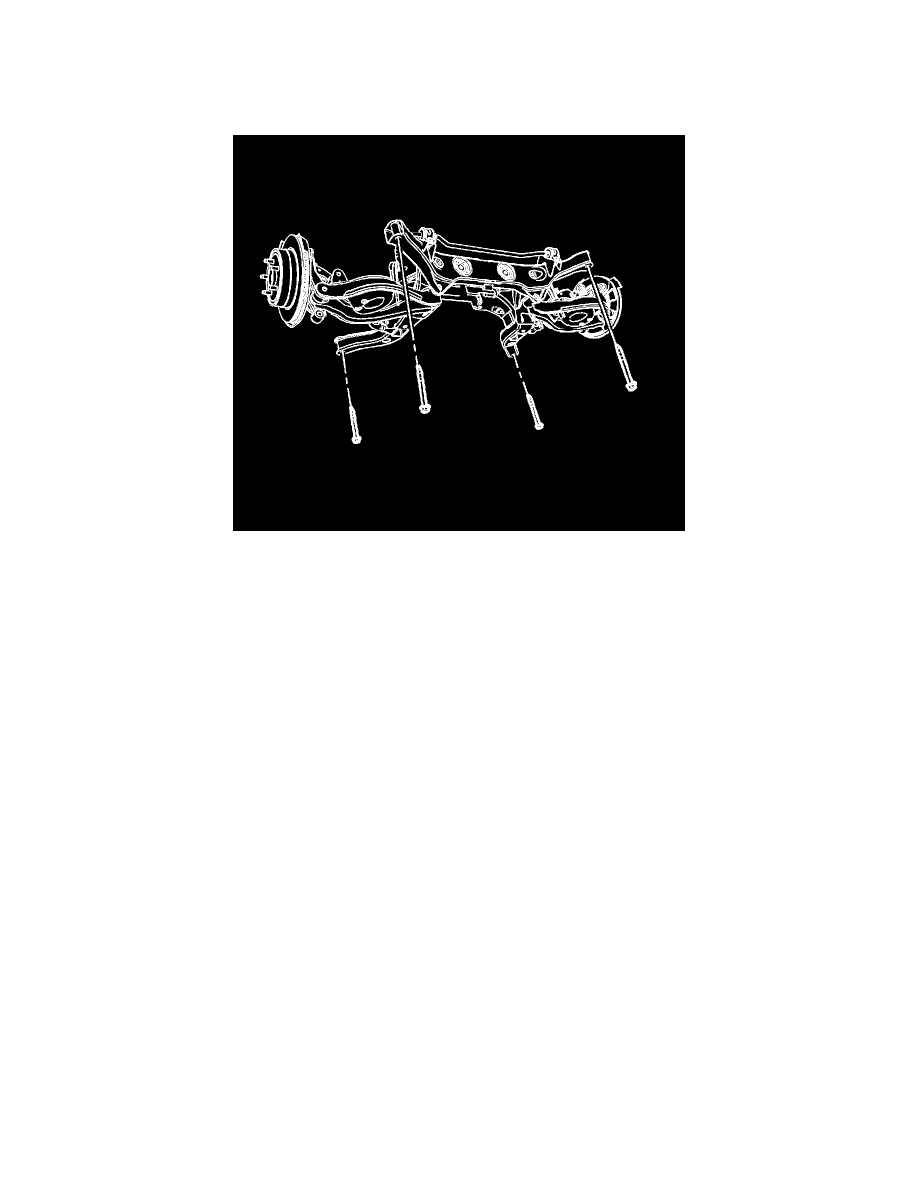
17. Position a transmission jack under the rear support and firmly secure the support to the jack with straps.
18. Remove the 4 rear support to body bolts.
19. Remove the rear support assembly from the vehicle.
20. With the aid of an assistant, remove the rear support from the transmission jack and place it on the floor.
Installation Procedure
Notice: Refer to Fastener Notice .
1. If a new rear support is being installed, a transfer of components is necessary.
*
Upper Control Arms
Tighten the upper control arm to rear support nut and bolt to 160 N.m (118 lb ft).
*
Lower Control Arms
Tighten the lower control arm to rear support nut and bolt to 110 N.m (81 lb ft).
*
Stabilizer bar and insulators
-
Tighten the stabilizer shaft insulator clamp bolts to 70 N.m (52 lb ft).
-
Tighten the stabilizer link to stabilizer shaft nut to 57 N.m (42 lb ft).
*
Knuckles - Loosely install the upper and lower control arm to knuckle nuts/bolts. These fasteners will be tightened later in this procedure after
the wheel driveshafts are installed.
2. With the aid of an assistant, position the rear support onto the transmission jack and firmly secure the support to the jack with straps.
3. Position the rear support assembly to the vehicle.