
Prizm L4-108 1.8L DOHC VIN 8 MFI (1998)
Ball Joint: Specifications
1. Raise and support the vehicle.
2. Place a jack stand under the suspension cross member.
3. Lower the vehicle slightly so the weight of vehicle rests on the suspension crossmember and not the control arms.
4. Remove the steering knuckle with the axle hub. Refer to STEERING KNUCKLE REPLACEMENT.
5. Clamp the steering knuckle with the axle hub in a soft-jawed vise.
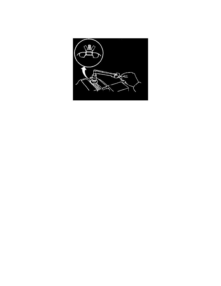
6. Inspect the movement of the ball stud by moving the ball stud back and forth five times.
NOTICE: Always use the correct fastener in the proper location. When you replace a fastener, use ONLY the exact part number for that
application. The manufacturer will call out those fasteners that require a replacement after removal. The manufacturer will also call out the
fasteners that require thread lockers or thread sealant. UNLESS OTHERWISE SPECIFIED, do not use supplemental coatings (paints, greases, or
other corrosion inhibitors) on threaded fasteners or fastener joint interfaces. Generally, such coatings adversely affect the fastener torque and joint
clamping force, and may damage the fastener. When you install fasteners, use the correct tightening sequence and specifications. Following these
instructions can help you avoid damage to parts and systems.
7. Use a torque wrench in order to turn the nut continuously for one turn every 2 - seconds.
8. Take the torque reading on the fifth turn.
Reading
The reading should be 1.0-2.9 Nm (9-26 inch lbs.).
9. If the movement of the ball stud is not within the specification, replace the ball stud. Refer to LOWER BALL JOINT REPLACEMENT (ABS
EQUIPPED VEHICLES).