
Silverado 2500 2WD V8-8.1L VIN G (2005)
46. Align the bolts holes and alignment tabs of pressure switch assembly (1) with the pressure switch assembly holes in main valve body (1).
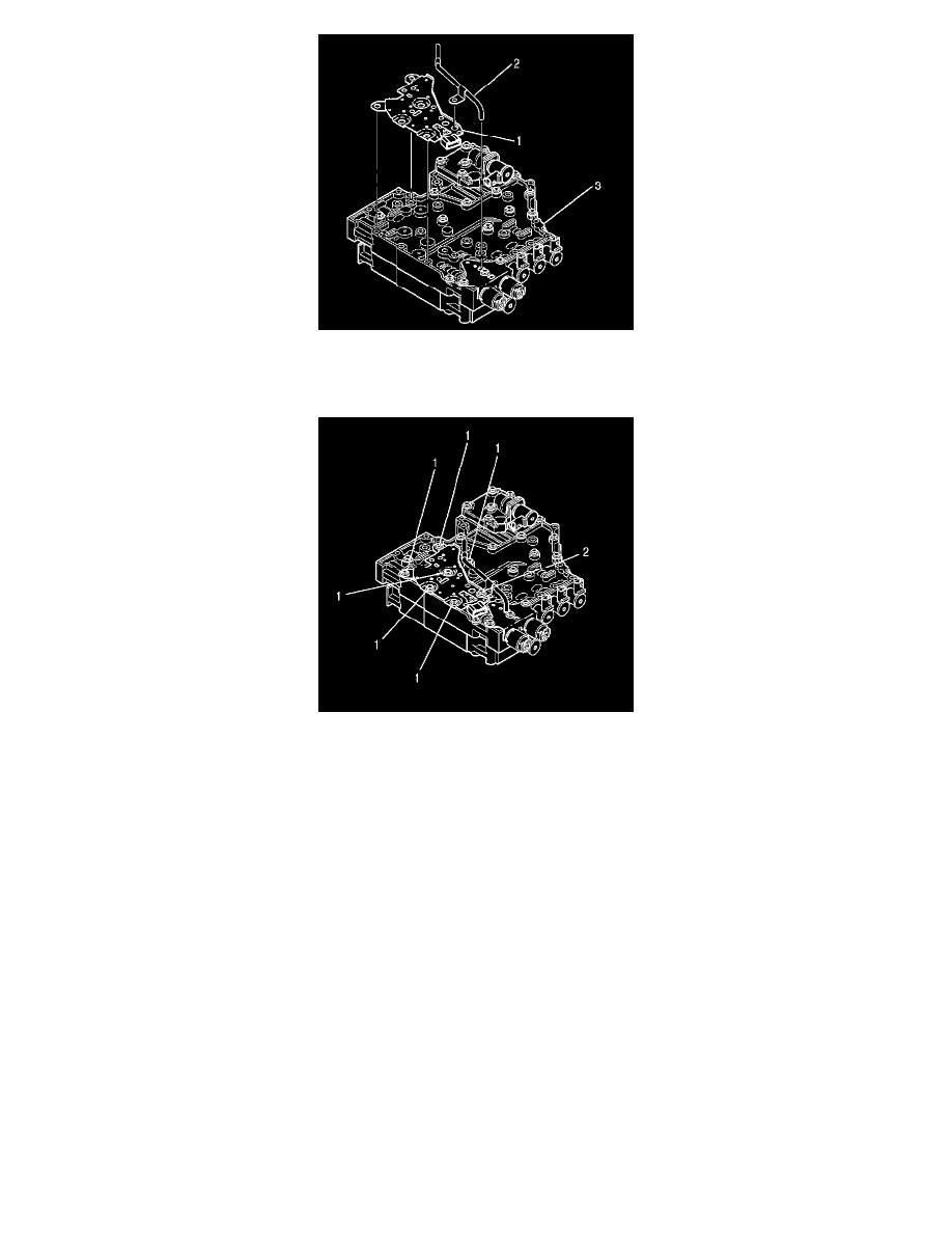
47. Install pressure switch assembly (1) onto main valve body (3).
48. Install reverse signal tube (2) onto the main valve body.
49. Important: Seven bolts retain the reverse signal tube and the pressure switch assembly.
^
Bolt (2) is slightly longer than the other bolts (1).
^
The pressure switch assembly is retained by five bolts (1) and by bolt (2).
^
The reverse signal tube is retained by one bolt (1) and by bolt (2).
Install six bolts (1) and one bolt (2) retaining the reverse signal tube and the pressure switch assembly to the main valve body.
^
Tighten bolts (1) and bolt (2) to 12 Nm (108 inch lbs.).
Control Main Filter Attachment Tube Replacement
Control Main Filter Attachment Tube Replacement
Removal Procedure
Important:
^
DO NOT drain the fluid if only the control main filter attachment tube is being replaced.
^
Use a standard strap-type filter wrench to remove or install the control main filter.