
Tracker 4WD L4-1.6L VIN 6 (1998)
Description
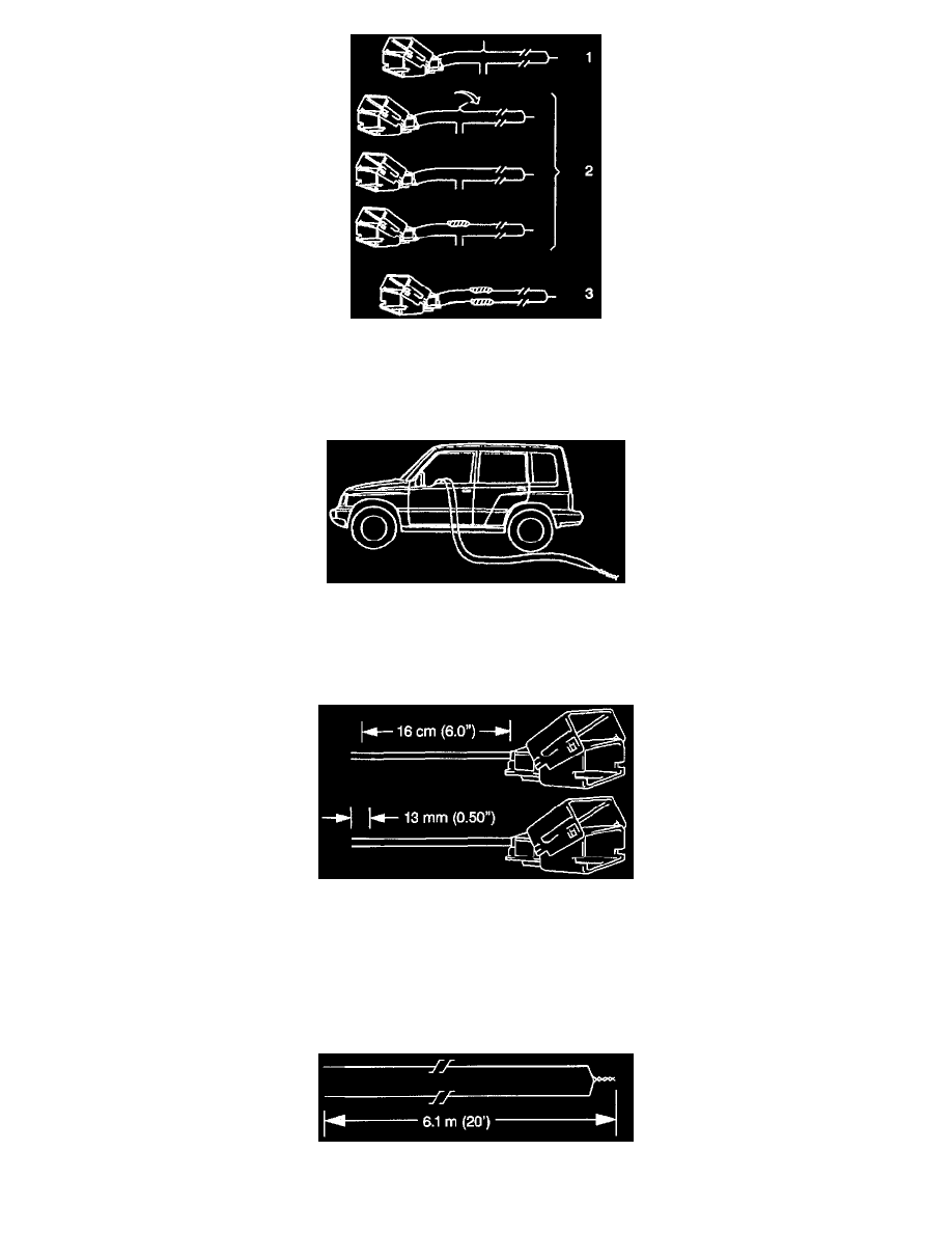
11. Twist together one connector wire lead to one deployment wire (1). Secure the connection mechanically.
12. Bend the twisted connection (2) flat. Wrap the connection tightly and securely with electrical tape. The tape will also insulate the connection.
13. Secure the remaining connector wire lead (3) to the remaining deployment wire.
Description
14. Connect the deployment harness to the inflatable restraint steering wheel module, yellow 2-way connector at the base of the steering column.
15. Route the deployment harness out of the driver side of the vehicle.
16. Disconnect the inflatable restraint IP module, yellow 2-way connector. This connector is located behind the IP compartment.
17. Cut the inflatable restraint IP module harness connector from the vehicle. Leave at least 160 mm (6 in) of wire at the connector.
18. Strip 13 mm (0.5 in) of insulation from each wire lead of the connector.
19. Cut two 6.1 m (20 ft) deployment wires from 0.8 mm[square] (18 gauge) or thicker multi-strand wire. Use these wires in order to fabricate the
driver deployment harness.
20. Strip 13 mm (0.5 in) of insulation from both ends of these two wires.
CAUTION: When you are deploying an inflator module for disposal, perform the deployment procedures in the order listed. Failure to
follow the procedures in the order listed may result in personal injury.
21. Short the wires by twisting together one end from each. Keep the deployment wires shorted. Do not connect these wires to a power source until
you are ready to deploy the air bag.