
Tracker 4WD L4-2.0L VIN C (1999)
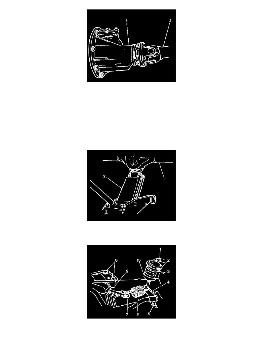
Important: To ensure rear propeller shaft balance, an index mark (reference mark) must be placed on the differential pinion flange and the rear
propeller shaft flange so that the rear propeller shaft can be installed in the same position from which it was removed. If this procedure is not followed,
a driveline imbalance may result causing vibration, premature component wear or other undesirable characteristics.
11. Remove the following from the vehicle:
^
The 4 bolts
^
The 4 nuts
^
The rear propeller shaft (2)
^
Loosen both rear control arm through bolts and nut.
^
Loosen the rear axle tie rod through bolt and nut.
^
Remove the drain pan from under the rear axle housing.
^
Lower the vehicle so that the rear axle housing may be supported with a hydraulic jack.
12. Support the rear axle housing (1) with a suitable hydraulic floor jack (2).
13. Remove the 4 bolts from the rear control arm ball joint boss. Separate the rear control arm ball joint boss from the differential carrier. Refer to
Rear Axle Lower Control Arm Replacement
14. If the vehicle does not have ABS, remove the bolt (5) in order to separate the load sensing proportioning valve from the rear axle.