
Tracker 4WD V6-2.5L VIN 4 (2001)
Ignition Relay: Testing and Inspection
IGNITION RELAY DIAGNOSIS
CIRCUIT DESCRIPTION
The ignition relay, also called the main relay, is controlled by the Powertrain Control Module (PCM). The PCM provides a ground for the relays coil
anytime the ignition switch is ON. The main relay supplies ignition positive voltage to many engine control systems and components. The following
components receive power from the main relay:
^
The fuel pump relay
^
The fuel injectors
^
The Mass Air Flow (MAF) sensor
^
The Evaporative Emission (EVAP) control system solenoids
^
The Exhaust Gas Recirculation (EGR) valve
^
The Idle Air Control (IAC) valve
^
The Powertrain Control Module (PCM)
DIAGNOSTIC AIDS
Check for any of the following conditions:
^
Check the resistance of the main relay. The resistance across terminal 3 and terminal 5 is 79-95 ohms at 20°C (68°F). The resistance across
terminal 1 and terminal 2 is infinite.
^
The main relay electrical contacts may be pitted or sticking. Replace the main relay if tapping gently on the relay or wiggling the relay causes a
change in the relays operation.
^
The performance of the main relay may be affected by temperature. Check the main relay after sitting outside overnight and after running the
engine 30 minutes.
^
Check for a faulty electrical connection to the PCM.
An intermittent malfunction may be caused by a fault in the main relay electrical circuit. Inspect the wiring harness and components for an intermittent
condition. Refer to Intermittent Conditions. See: Powertrain Management/Computers and Control Systems/Testing and Inspection/Initial Inspection
and Diagnostic Overview/Diagnostic Strategies/Intermittent Conditions
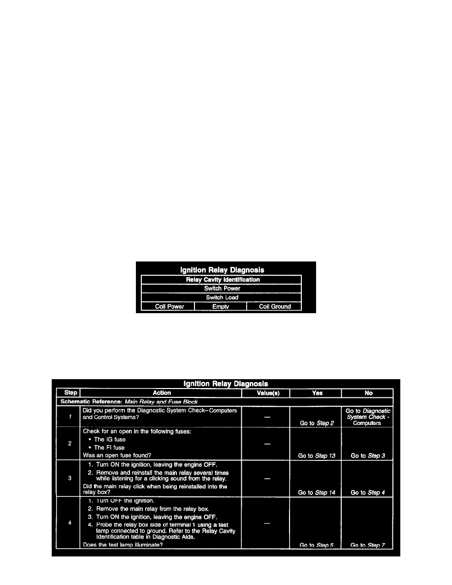
Ignition Relay Diagnosis
Use the above relay cavity table in order to locate the correct cavities to probe during diagnosis. The table layout corresponds to the cavity layout of
the relay block.
TEST DESCRIPTION