
Concorde V6-2.7L VIN V (2001)
CAUTION: Do not apply a 12-volt power source to any terminals of the 25-way HCU connector when disconnected from the CAB.
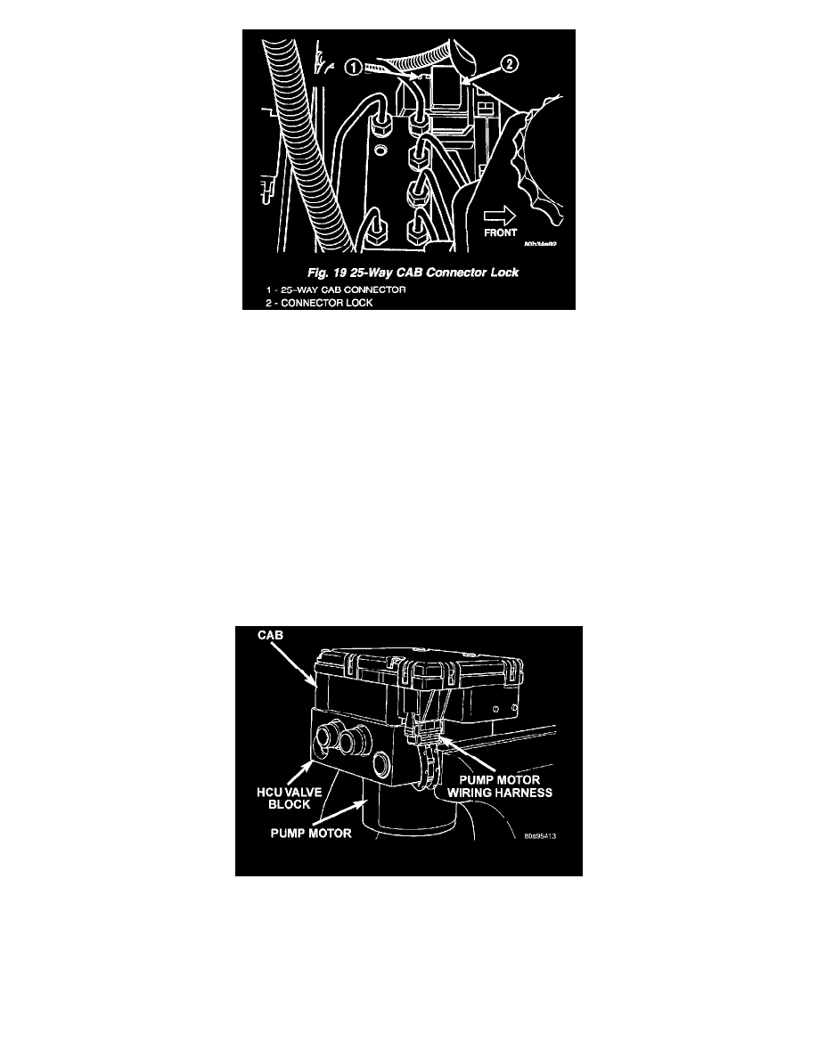
10. Disconnect the 25-way wiring harness connector from the CAB using the following procedure. Grasp the lock on the 25-way connector, and pull it
up from the connector as far as possible. This will unlock and raise the 25-way connector out of the socket on the CAB.
11. Raise vehicle.
12. Remove the left front tire and wheel assembly.
13. Remove fasteners securing the inner fender splash shield in place. Move the splash shield out of the way.
14. Remove the 3 bolts attaching the ICU to the mounting bracket.
15. Remove the ICU from its mounting bracket. Then, remove the ICU from the vehicle by pulling it out around the left side of the mounting bracket,
then through the wheel well.
NOTE: To separate the CAB from the HCU
DISASSEMBLY - ICU
NOTE: To replace the Hydraulic control unit (HCU) or the Controller Antilock Brake (CAB) on this vehicle, the entire Integrated Control Unit
(ICU) needs to be removed from the vehicle. The CAB can then be separated from the HCU. Do not attempt to replace the CAB with the ICU
mounted in the vehicle.
1. Remove the ICU from the vehicle. Refer to REMOVAL.
Pump/Motor To CAB Wiring Harness
2. Disconnect the pump/motor wiring harness from the CAB.