
PT Cruiser L4-2.4L Turbo VIN 8 (2005)
from the vehicle.
8. Disconnect the two brake tubes from the master cylinder primary and secondary ports (Fig. 22). Install plugs at all of the open brake tube outlets
on the master cylinder.
9. Disconnect and remove the primary and secondary brake tubes coming from the master cylinder at the ICU hydraulic control unit (HCU) (Fig. 22).
10. Clean the area around where the master cylinder attaches to the power brake booster using a suitable brake cleaner such as Mopar Brake Parts
Cleaner or equivalent.
11. Remove the two nuts attaching the master cylinder to the power brake booster.
12. Slide the master cylinder straight out of the power brake booster.
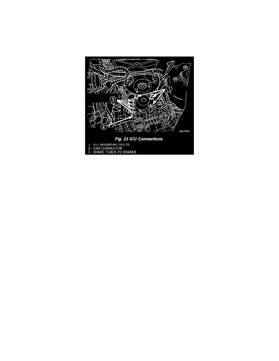
13. Disconnect the brake tubes going to each individual brake at the HCU (Fig. 23).
14. Disconnect the 24-way connector from the controller antilock brake (CAB) mounted on the integrated control unit (ICU) and move it out of the
way (Fig. 23). The connector is disconnected by pulling outward on the connector lock. This will unlock and raise the 24-way connector out of the
socket on the CAB.
15. Remove the 3 bolts attaching the ICU to its mounting bracket (Fig. 23).
16. Remove the ICU from the vehicle.
17. To separate the CAB from the HCU, Refer to ICU - Disassembly and Assembly.
INSTALLATION
1. Install the ICU onto its mounting bracket.
2. Install the 3 bolts attaching the ICU to the mounting bracket (Fig. 23). Tighten the 3 mounting bolts to a torque of 11 Nm (97 inch lbs.)
CAUTION: Before installing the 24-way connector in the CAB, be sure the seal is properly installed in the connector.
3. Install the 24-way connector into the socket of the CAB as follows:
^
Position the 24-way connector in the socket of the CAB and carefully push it down as far as possible (Fig. 23).
^
When the connector is fully seated into the CAB socket, push the connector lock inward. This pulls the connector into the socket of the CAB
and locks it in the installed position.
4. Install the four brake tubes going to the brakes into their respective outlet ports on the ICU HCU (Fig. 23). Using a crow foot on a torque wrench,
tighten the four brake tube nuts to a torque of 17 Nm (145 inch lbs.).
5. Wipe the face of the power brake booster clean where the master cylinder seal comes in contact when it's installed. Do not get any cleaner or
debris inside the booster.
6. Position the master cylinder on the studs of the power brake booster, aligning the push rod of the power brake booster with master cylinder piston
push rod. Carefully push the master cylinder onto the studs until it contacts the face of the booster.
7. Install the two master cylinder mounting nuts and tighten each to a torque of 18 Nm (160 inch lbs.).
NOTE: When installing the brake tubes from the master cylinder on the HCU, the brake tube with the small tube nut is to be installed in the
forward-most port on the HCU with the small end going toward the master cylinder secondary port.
8. Install the primary and secondary brake tubes from the master cylinder onto the HCU (Fig. 22). Do not completely tighten the primary and
secondary tubes at this time.
9. Connect the two brake tubes to the master cylinder primary and secondary ports (Fig. 22).
10. Using a crow foot on a torque wrench, tighten the primary and secondary brake tube nuts at both the master cylinder and HCU to a torque of 17
Nm (145 inch lbs.).
11. Connect the brake fluid level switch wiring connector.
12. Install the power distribution center.