
Lanos S Hatchback L4-1.6L DOHC D-TEC MFI (1999)
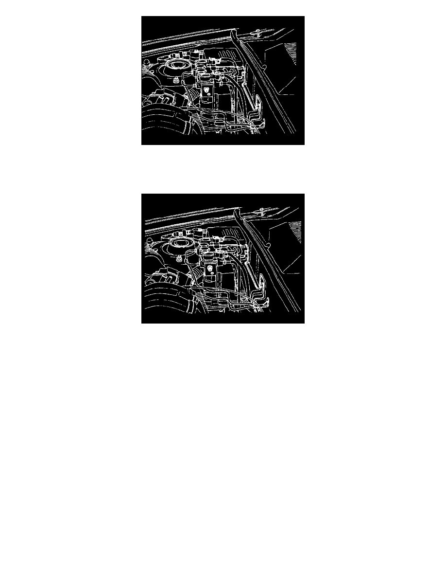
2. Unscrew and remove the bleeder valve from the hydraulic modulator. This illustration shows the left-side bleeder valve. There is another bleeder
valve on the right side.
Installation Procedure
1. Install the bleeder valve into the hydraulic modulator. Do not tighten fully.
2. Bleed the brake system. See: Brake Bleeding
Gear Tension Relief Sequence
GEAR TENSION RELIEF SEQUENCE
Tools Required
Scan Tool
When the displacement cylinder pistons are in the topmost (home) position, each motor has prevailing torque due to the force necessary to ensure each
piston is held firmly at the top of its travel. This torque results in gear tension, or force on each gear that makes motor pack separation difficult. To
avoid injury or damage to the gears, the gear tension relief sequence briefly reverses each motor to eliminate the prevailing torque.
Always perform the gear tension relief sequence prior to removing the hydraulic modulator from the vehicle. Each hydraulic modulator gear (the large
gears) should be free to turn in one direction and then in the other direction when the motor pack is removed. If any gear will not move, replace the
hydraulic modulator. Refer to "Hydraulic Modulator/Motor Pack Assembly". See: Hydraulic Modulator/Motor Pack Assembly
Hydraulic Modulator/Motor Pack Assembly
HYDRAULIC MODULATOR/MOTOR PACK ASSEMBLY
WARNING: To help avoid personal injury due to the retained load on the hydraulic modulator/motor pack assembly, perform the gear
tension relief function of the scan tool before removing the hydraulic modulator/motor pack assembly.
Removal Procedure
1. Using the scan tool, perform the gear tension relief sequence. See: Gear Tension Relief Sequence
2. Disconnect the negative battery cable.