
Durango 4WD V8-5.9L VIN Z (1998)
Throttle Body: Service and Repair
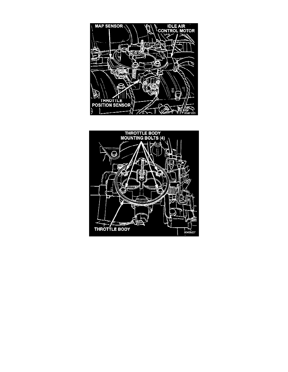
Fig 68 Sensor Electric Connectors - Typical
Fig 69 Throttle Body Mounting Bolts - Typical
CAUTION: A (factory adjusted) set screw is used to mechanically limit the position of the throttle body throttle plate. Never attempt to adjust the
engine idle speed using this screw. All idle speed functions are controlled by the powertrain control module (PCM).
REMOVAL
1. Remove the air duct at throttle body.
2. Disconnect throttle body electrical connectors at MAP sensor, IAC motor and TPS (Fig. 68).
3. Remove vacuum line at throttle body
4. Remove all control cables from throttle body (lever) arm. Refer to the Accelerator Pedal and Throttle Cable for additional information.
5. Remove four throttle body mounting bolts (Fig. 69).
6. Remove throttle body from intake manifold.
7. Discard old throttle body-to-intake manifold gasket.
INSTALLATION
1. Clean the mating surfaces of the throttle body and the intake manifold.
2. Install new throttle body-to-intake manifold gasket.
3. Install throttle body to intake manifold.
4. Install four mounting bolts. Tighten bolts to 23 Nm (200 in lb) torque.
5. Install control cables.
6. Install vacuum line to throttle body.
7. Install electrical connectors.