
Durango 4WD V8-5.9L VIN Z (1998)
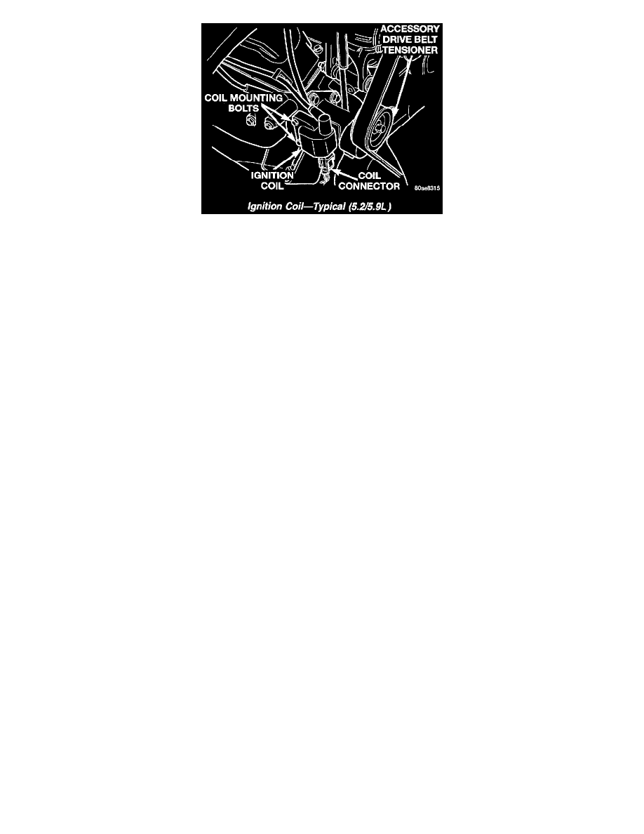
Ignition Coil - Typical
To perform a complete test of the ignition coil and its circuitry, refer to the DRB scan tool. Also refer to the appropriate Powertrain Diagnostics
Procedures. To test the coil only, refer to the following:
The ignition coil is designed to operate without an external ballast resistor.
Inspect the ignition coil for arcing. Test the coil according to coil tester manufacturer's instructions. Test the coil primary and secondary resistance.
Replace any coil that does not meet specifications. Refer to the IGNITION COIL RESISTANCE chart.
Ignition Coil Resistance
Coil Manufacturer = Diamond
Primary Resistance 21-27° C (70-80° F) = 0.97 - 1.18 Ohms
Secondary Resistance 21-27° C (70-80° F) = 11,300 - 15,300 Ohms
Coil Manufacturer = Toyodenso
Primary Resistance 21-27° C (70-80° F) = 0.95 - 1.20 Ohms
Secondary Resistance 21-27° C (70-80° F) = 11,300 - 13,300 Ohms
If the ignition coil is being replaced, the secondary spark plug cable must also be checked. Replace cable if it has been burned or damaged.
Arcing at the tower will carbonize the cable boot, which if it is connected to a new ignition coil, will cause the coil to fail.
If the secondary coil cable shows any signs of damage, it should be replaced with a new cable and new terminal. Carbon tracking on the old cable
can cause arcing and the failure of a new ignition coil.
Failure To Start Test
To prevent unnecessary diagnostic time and wrong test results, the Testing For Spark At Coil test should be performed prior to this test.
WARNING: SET PARKING BRAKE OR BLOCK THE DRIVE WHEELS BEFORE PROCEEDING WITH THIS TEST.
1. Unplug the ignition coil harness connector at the coil.
2. Connect a set of small jumper wires (18 gauge or smaller) between the disconnected harness terminals and the ignition coil terminals.
3. Attach one lead of a voltmeter to the positive (12 volt) jumper wire. Attach the negative side of voltmeter to a good ground. Determine that
sufficient battery voltage (12.4 volts) is present for the starting and ignition systems.
4. Determine that sufficient battery voltage (12.4 volts) is present for the starting and ignition systems.
5. Crank the engine for 5 seconds while monitoring the voltage at the coil positive terminal:
6.
-
If the voltage remains near zero during the entire period of cranking, refer to On-Board Diagnostics. Check the Powertrain Control Module
(PCM) and auto shutdown relay.
-
If voltage is at or near battery voltage and drops to zero after 1-2 seconds of cranking, check the powertrain control module circuit. Refer
to On-Board Diagnostics.