
Durango 4WD V8-5.9L VIN Z (1998)
Drive/Propeller Shaft: Removal and Replacement
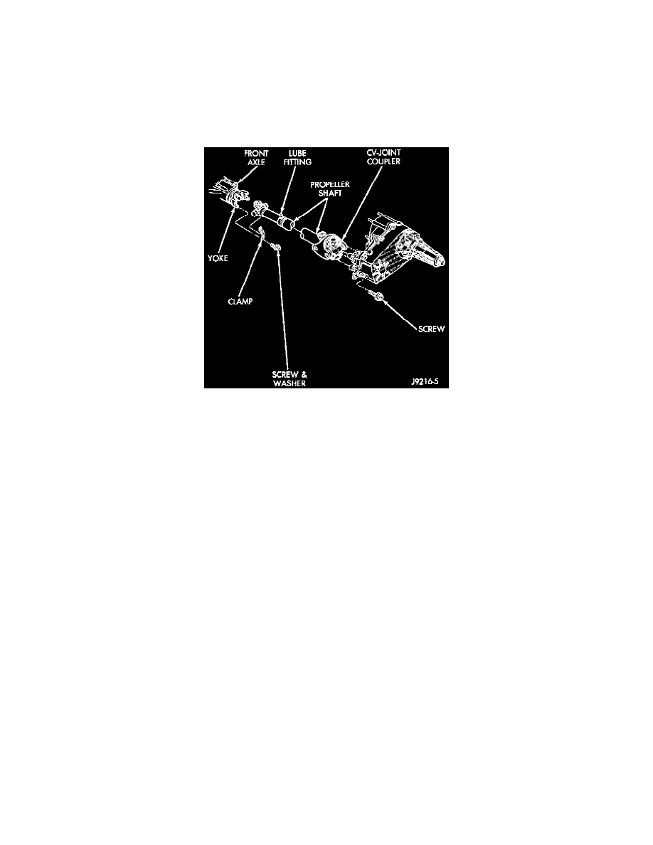
Front
REMOVAL
1. Shift the transmission and transfer case to their neutral positions. Raise and support vehicle. Remove skid plate, if equipped.
2. Using a suitable marker, mark a line across the yoke at the transfer case, the link yoke, and propeller shaft yoke at the rear of the front propeller
shaft for installation reference.
3. Mark a line across the propeller shaft yoke and the pinion shaft yoke for installation reference.
Front Propeller Shaft
4. Remove the universal joint strap bolts at the pinion shaft yoke.
5. Remove the bolts holding the propeller shaft to the transfer case yoke.
6. Remove the propeller shaft.
INSTALLATION
1. Position front propeller shaft under vehicle with rear universal joint over the transfer case yoke flange.
2. Place front universal joint into the axle pinion yoke.
3. Align mark on the link yoke and universal joint to the mark on the transfer case yoke flange.
4. Loosely install bolts to hold universal joint to transfer case yoke.
5. Align mark on front universal joint to the mark on the axle pinion yoke.
6. Install bolts to hold front universal joint to axle pinion yoke. Tighten bolts to 19 Nm (14 ft. lbs.).
7. Tighten bolts to hold universal joint to transfer case yoke to 27 Nm (20 ft. lbs.).
8. Install skid plate, if equipped.
9. Lower vehicle and road test to verify repair.
Rear
REMOVAL
1. Raise and support vehicle on safety stands.
2. Shift the transmission to the Neutral position.
3. Using a suitable marker, mark a line across the axle pinion yoke and the propeller shaft yoke for installation reference.
4. Using a suitable marker, mark the outline of the center bearing on the support bracket for installation reference, if equipped.
5. Using a suitable marker, mark the outline of the heat shield on the center bearing for installation reference, if equipped.
6. Remove bolts that attach the center bearing and heat shield to the support bracket, if equipped.
7. Remove the bolts holding the universal joint clamps to the pinion yoke.