
Intrepid V6-3.2L VIN J (1998)
Antenna: Testing and Inspection
NOTE: Due to a capacitor integral with the coaxial cable, the coax cable can not be tested. The continuity test between the center pin of the coax to the
antenna does not apply. An ohm meter check to the center pin of the coaxial cable will falsely indicate an open circuit. The coaxial shield to ground test
can be performed. Verify coaxial cable performance by using a known good cable.
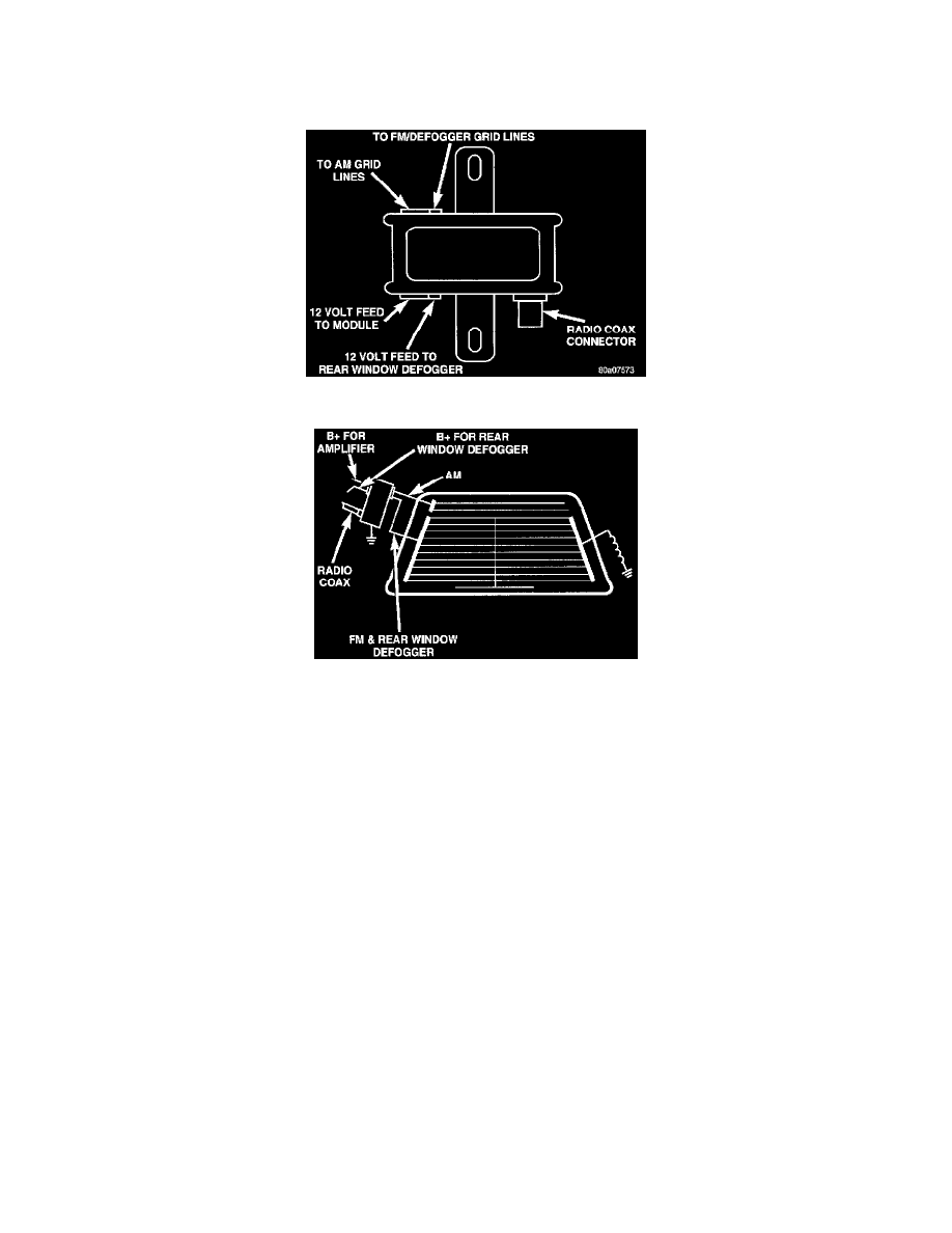
Rear Window Antenna Module
Rear Window Grid Lines And Module
Before performing any antenna service procedures, verify that Rear Window Defogger is operating properly. If no, repair as necessary.
1. Check that the rear window adhesive does not come in contact with any portion of the grid lines or bus bars. There should be a minimum of 2 mm
gap between adhesive and the grid lines or bus bars. If not OK, repair as necessary If OK, go to Step 3.
2. Check for proper radio coaxial cable connections at the radio and rear window antenna module. If not OK, repair as necessary If OK, go to Step 4.
3. Loss of reception on only one band (AM or FM) may indicate a continuity problem on the rear window grids. Test the grid lines with an
ohmmeter. If not OK, repair grid lines as necessary. If OK, go to Step 5.
4. Turn the radio and rear window defogger ON position. Using a voltmeter, test for battery voltage at the X60 and C15 circuit terminals of the rear
window antenna module wire harness connector. If not OK, check fuses, if fuses are OK, repair wire harness as necessary.
5. Ensure that the rear window defogger ground wire with integral coil in the C-pillar has a good ground.
6. If not OK, repair as necessary If OK, go to Step 8.
CAUTION: Rear Window Defogger must be in the OFF position
7. Quick check of the module:
-
Place the ignition switch in the ACC position with the radio in the ON position on a appropriate station (AM/FM).
-
Tune to a AM station
-
Using a grounded jumper wire, momentarily short the AM lead to the grid lines.
-
There should be an audible CRACKLE through the speakers indicating circuit continuity.
-
Tune to a FM station
-
Using a grounded jumper wire, momentarily short the FM lead to the grid lines.
-
There should be an audible CRACKLE through the speakers indicating circuit continuity.
If not OK, go to Step 9.If OK, go to Step 10.
8. Using a ohmmeter, check continuity between the module wire connector and:
-
AM grid lines
-
FM/rear window antenna grid lines
If not OK, repair necessary Refer Window and Glass/Heated Glass Element/Electrically Heated Systems, If OK, go to Step 10.
9. If neither AM or FM can be received, use a known good radio and verify If not OK, use a known good antenna module and verify If OK, either