
RAM 1500 Truck 4WD V8-5.9L VIN Z (2002)
General Information (Part 2 of 2)
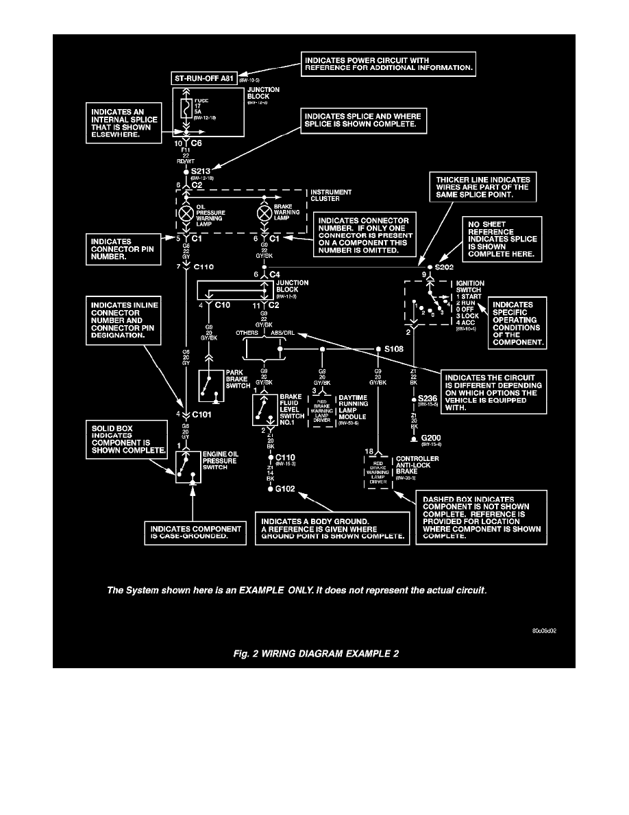
All switches, components, and modules are shown in the at rest position with the doors closed and the key removed from the ignition (Fig. 2).
Components are shown two ways. A solid line around a component indicates that the component is complete. A dashed line around the component
indicates that the component is being shown is not complete. Incomplete components have a reference number to indicate the page where the component
is shown complete.
It is important to realize that no attempt is made on the diagrams to represent components and wiring as they appear on the vehicle. For example, a short