
RAM 1500 Truck 4WD V8-5.9L VIN Z (2002)
INTERMEDIATE SHAFT SPACER SELECTION
1. Place overdrive unit in vertical position. Mount it on blocks, or in workbench with appropriate size mounting hole cut into it. Be sure unit is facing
upward for access to direct clutch hub. Also be sure output shaft is not loaded and internal components are moved rearward for accurate
measurement.
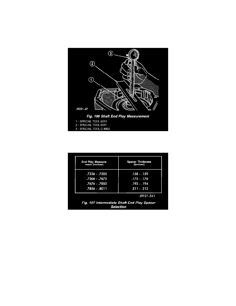
2. Determine correct thickness intermediate shaft spacer as follows:
a. Insert Special Tool 6312 through sun gear, planetary gear and into pilot bushing in output shaft. Be sure tool bottoms against planetary
shoulder.
b. Position Gauge Tool 6311 across face of overdrive case (Fig. 196). Then position Dial Caliper C-4962 over gauge tool.
c. Extend sliding scale of dial caliper downward through gauge tool slot until scale contacts end of Gauge Alignment Tool 6312. Lock scale in
place. Remove dial caliper tool and note distance measured (Fig. 196).
d. Select proper thickness end play spacer from spacer chart based on distance measured (Fig. 197).
e. Remove Gauge Alignment Tool 6312.
OD THRUST PLATE SELECTION
1. Place overdrive unit in vertical position. Mount it on blocks, or in workbench with appropriate size mounting hole cut into it. Be sure unit is facing
upward for access to direct clutch hub. Also be sure output shaft is not loaded and internal components are moved rearward for accurate
measurement.
2. Determine correct thickness overdrive piston thrust plate as follows: