
Rampage L4-135 2.2L (1983)
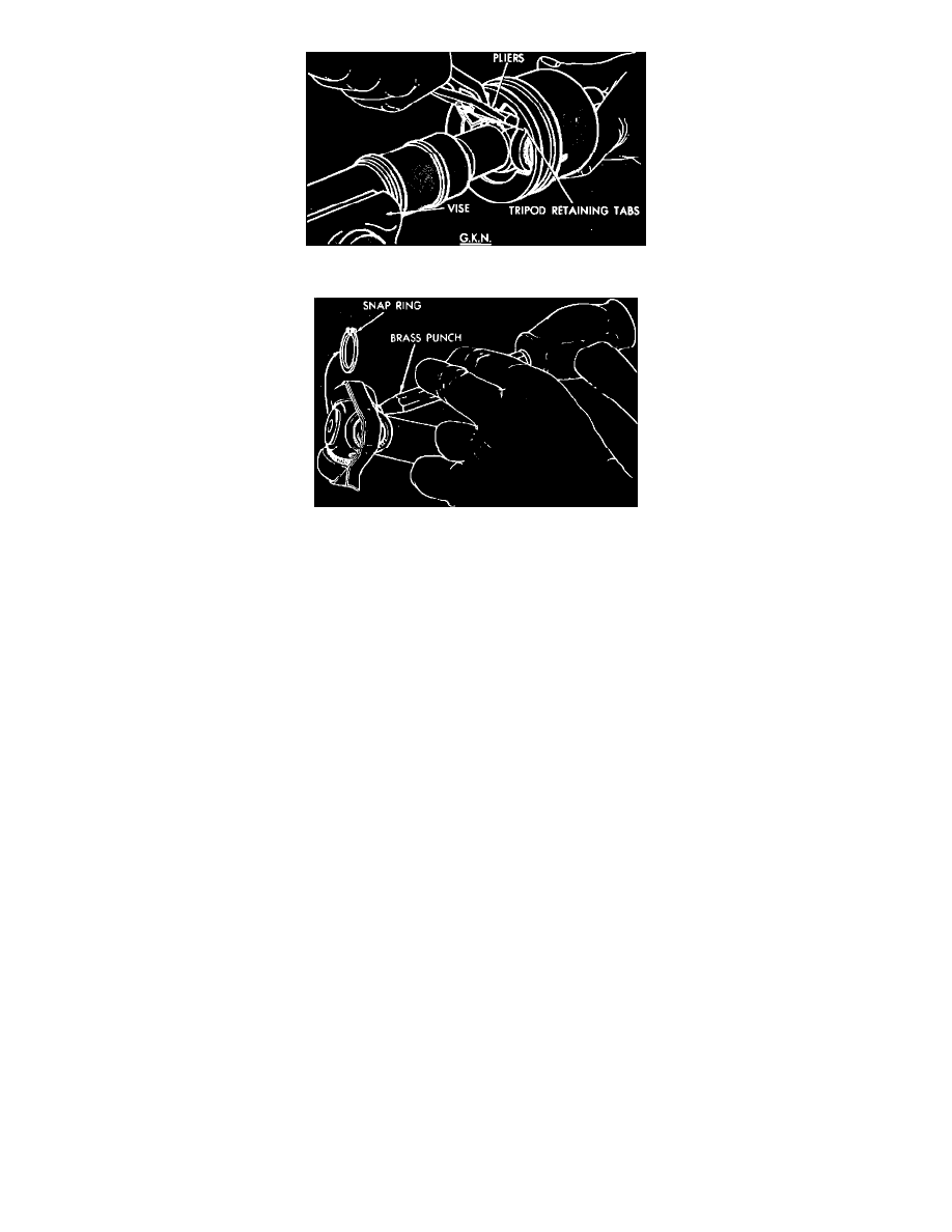
Fig. 34 Removing inner C/V joint tripod housing. Late model G.K.N. units
Fig. 35 Removing snap ring & tripod inner C/V joints
3. On early 1982 G.K.N. non-spring loaded units, slide tripod from housing. On late 1982 - 84 G.K.N. spring loaded units, bend tabs on joint cover
using needle nose pliers, then remove tripod from housing.
4. Remove snap ring from end of shaft, then remove tripod using brass punch.
INSPECTION
Remove grease from assembly and inspect bearing race and tripod components for wear and damage and replace as necessary. On late 1982 - 84
spring loaded joints inspect spring, spring cup and spherical end of connecting shaft for wear and damage and replace as necessary.
Components of spring loaded and nonspring loaded inner C/V joints cannot be interchanged.
ASSEMBLY
1. Slide small end of boot over shaft. On tubular type shafts, align boot lip with mark on shaft outer diameter. On solid type shafts, position small end
of boot in groove on shaft.
2. Place rubber clamp over groove on boot.
3. Install tripod on shaft with non-chamfered face of tripod body facing shaft retainer groove.
4. Lock tripod assembly on shaft by installing retaining ring in shaft groove.
5. Distribute packets of special grease provided in boot and clamp kit as follows:
a. On early 1982 G.K.N. units, distribute one packet of grease in housing before positioning housing over tripod.
b. On late 1982 - 84 G.K.N. units, distribute one packet of grease in housing, then position spring with spring cup attached to exposed end into
spring pocket. Place a small amount of grease on spring cup.
c. On A.C.I. units, distribute one packet of grease in boot and remaining packet in housing.
6. On early 1982 G.K.N. units, slip tripod into housing, then install boot over housing groove.
7. On late 1982 - 84 G.K.N. units, slip tripod into housing and bend retaining tabs down to their original position. Install boot over housing and
ensure retaining tabs hold tripod in housing.
8. On A.C.I. units, align tripod roller with retaining tabs and housing tracks. Install one roller at a time through retaining tabs, and bend retaining tabs
down into their original position. Install boot over housing and ensure retaining tabs hold tripod in housing. On all spring loaded joints, check to
ensure spring remains in pocket and centered in housing. Also ensure spring cup contacts spherical end of connecting shaft.
9. On all models, install boot clamp.