
Rampage L4-135 2.2L (1983)
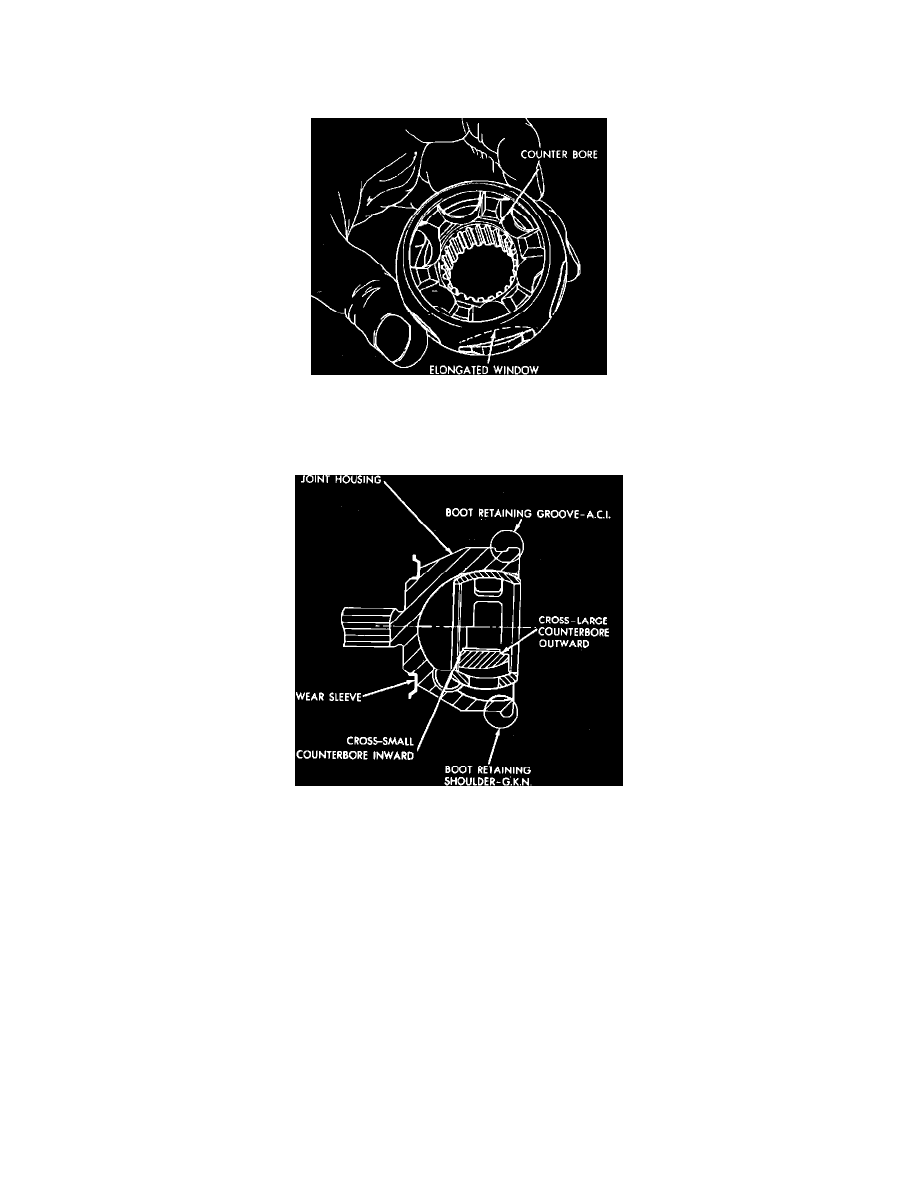
Fig. 36 Outer C/V joint disassembled
1. If removed, position wear sleeve on joint housing, then tap sleeve onto housing, using tool No. C-4698.
2. Lightly oil components, then align marks made during disassembly.
Fig. 42 Cage & cross assembly. Outer C/V joints
3. Align one of the inner race lands with elongated window of cage, then insert race into cage and pivot 90°.
4. Align elongated cage windows with housing land, then pivot cage 90
Fig. 43 Cage & cross assembly installed in housing. Outer C/V joints
°. The curved side of the elongated cage windows and inner race counterbore should face outward from joint.
5. Lubricate ball races with one packet of grease from kit.
6. Tilt cage and inner race assembly and insert balls.
7. With shaft supported in a soft jawed vise, install boot.
8. Slide small end of boot over spacer ring and shaft, then position boot end in machined groove.
9. Install snap ring on shaft. When installing use care not to overexpand snap ring.
10. Position joint housing on shaft, then engage by tapping sharply with a soft-faced mallet.
11. Check to ensure that snap ring is properly seated, by attempting to pull joint from shaft.
12. Locate large end of boot over housing.
13. On G.K.N. units, secure boot clamps using tool No. C-4124.
Inspection
1. Check housing ball races for excessive wear.
2. Check splined shaft and nut threads for damage.
3. Inspect the balls for pitting, cracks, scoring and wearing. Dulling of the surface is normal.
4. Inspect cage for excessive wear on inner and outer spherical surfaces, heavy brinnelling of cage, window cracks and chipping.
5. Inspect inner race (Cross) for excessive wear or scoring of ball races.