
Stratus Coupe V6-3.0L VIN H (2001)
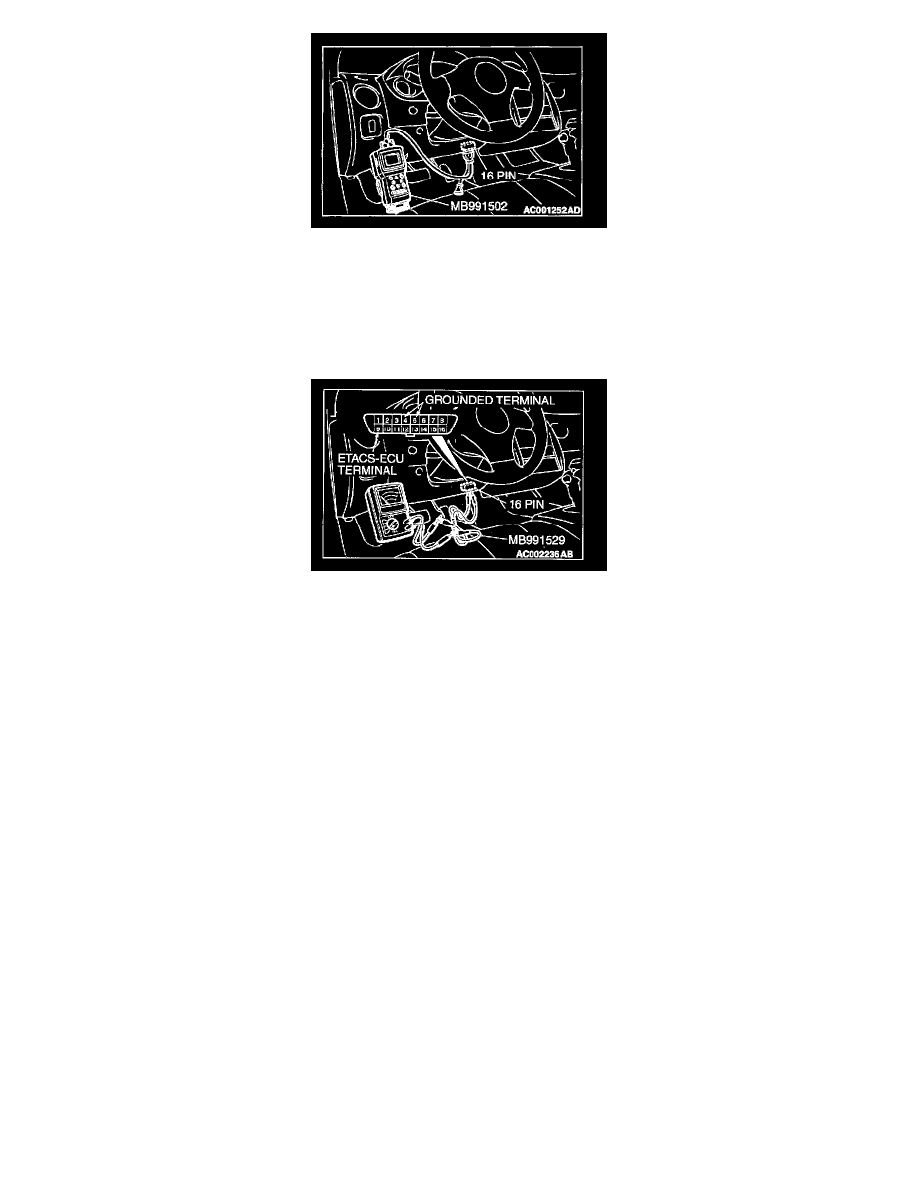
1. Connect scan tool MB991502 to the data link connector.
2. Check that the tone alarm of scan tool MB991502 sounds when the input signal enters.
Q: Does the tone alarm of scan tool MB991502 sound when the input signal enters?
YES: Replace the front-ECU. The passing switch should work normally.
NO: Check the passing switch input circuit. Refer to Inspection Procedure O-15.
STEP 3. Check the input signal (by using a voltmeter).
Check the input signal from the passing switch.
1. Use special tool MB991529 to connect a voltmeter between ground terminal 4 or 5 and ETACS-ECU terminal 9 of the data link connector.
2. Check that the voltmeter indicator deflects once when the input signal enters.
Q: Does the voltmeter indicator deflect?
YES: Replace the front-ECU. The passing switch should work normally.
NO: Check the passing switch input circuit. Refer to Inspection Procedure O-15.
Inspection Procedure J-5
Headlight, taillight: Headlight automatic shutdown function does not work normally.
TECHNICAL DESCRIPTION (COMMENT)
The ETACS-ECU and front-ECU operates the headlight automatic shutdown function, based on the signals from the following switches:
-
Ignition switch (IG1)
-
Taillight switch
-
Headlight switch
If the function does work normally, a defect on relevant input circuits, the ETACS-ECU or the front ECU is suspected.
TROUBLESHOOTING HINTS
-
Malfunction of the column switch (turn-signal light and lighting switch)
-
Malfunction of the ETACS-ECU
-
Malfunction of the front-ECU
-
Damaged harness wires or connectors
DIAGNOSIS