
Servicing the commutator
- Make
- Fiat
- Model
- 500 Classic Workshop Manual
- Year
- 1957–1975
- Section
- The generator › Servicing the commutator
Servicing the commutator
A commutator in good condition should be smooth and free from pitting or signs of the segments burning. Clean with a rag moistened in petrol. If necessary, polish using a fine glasspaper whilst rotating the armature. Never use emerycloth.
If the commutator is badly worn it may be skimmed using a centre lathe. Use a high rotational speed and take a light cut using a sharp tool. Remove only enough metal to clean up the commutator face and then polish with fine glasspaper. To undercut the insulation between the segments, it is suggested that a hacksaw blade is ground on its sides until it is the thickness of the insulation and carefully work between each pair of segments until the insulation has been cut to a depth of .0394 inch below the surface.
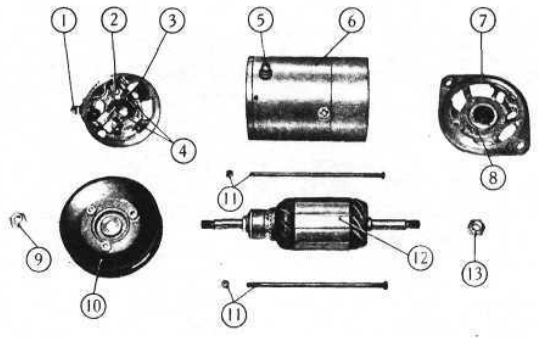
| 1 | Terminal 51 |
| 2 | Bearing outer ring retainment terminal nut |
| 3 | Commutator end head |
| 4 | Brushes |
| 5 | Terminal 67 |
| 6 | Frame |
| 7 | Blower end head |
| 8 | Bearing retainer nuts and screws |
| 9 | Pulley retainment nut |
| 10 | Pulley |
| 11 | Head mounting tie rods and nuts |
| 12 | Armature |
| 13 | Blower retainment nut |
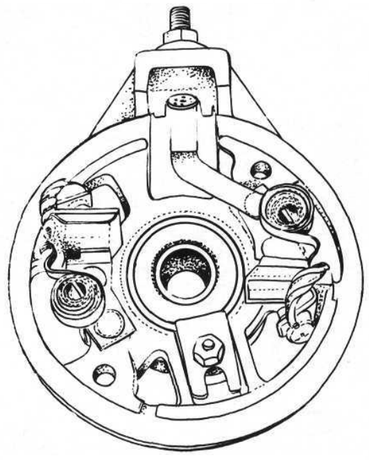
A thorough visual inspection may determine the cause of armature failure. Breaks in armature windings cause burnt commutator segments. Short-circuited windings are discoloured by overheating, with badly burnt commutator segments.
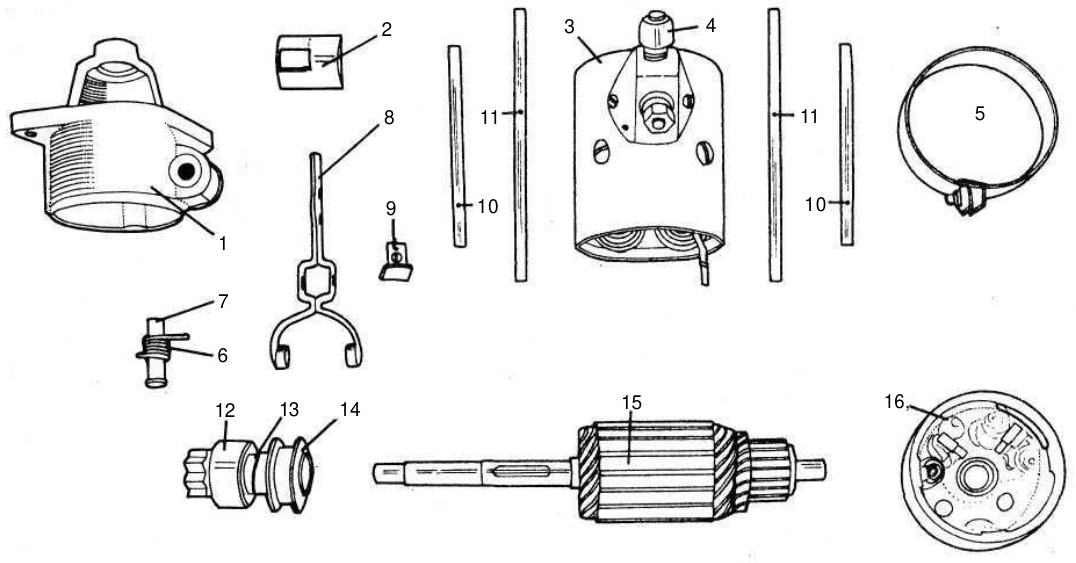
| 1 | Drive end head |
| 2 | Head shield |
| 3 | Frame |
| 4 | Switch |
| 5 | Commutator cover band |
| 6 | and |
| 7 | Pin and spring for lever 8 |
| 8 | Starting engagement lever |
| 9 | Head shield |
| 10 | and |
| 11 | Head fixing tie rods and tubes |
| 12 | Pinion, complete |
| 13 | Starting engagement spring |
| 14 | Drive unit sleeve and free wheel hub |
| 15 | Armature |
| 16 | Commutator end head |
Testing field coils
When tested with an ohmmeter the reading should be 8+.1—.3 ohms. Failing an ohmmeter use a 12-volt supply and connect it in series with an ammeter across the field terminal and the yoke or body. The meter should read approximately 2 amps. If there is no reading the field coil winding has a break in it. If the reading is much more than 2 amps or the ohmmeter records at much less than 8 ohms it shows that field coil insulation has broken down. Renewal of the field coils is a specialist operation best left to a service station.
Parts & tools for this job For 1957 Fiat 500 Classic
- TOOLBattery testerSearch: car battery tester
- TOOLDigital multimeterSearch: automotive digital multimeter
- TOOLBattery terminal cleanerSearch: battery terminal cleaner
Links open Amazon search results in a new tab. As an Amazon Associate I earn from qualifying purchases.