
Heating/ventilation
- Make
- Fiat
- Model
- Bravo /Brava (182) Factory Service Manual
- Year
- 1995–2001
- Section
- Heating and ventilation › Heating/ventilation
Heating/ventilation
Air conditioning or adjustment of vehicle passenger compartment air temperature and humidity may be carried out by one of the following two systems:
- a manual heater fitted to the vehicle as standard;
- a manual air conditioner which may be fitted as an option to replace the original system.
HEATER WITH MANUAL CONTROLS
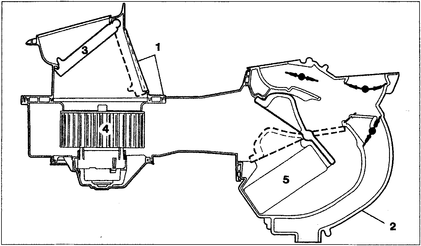
The assembly shown in cross section in the figure below is the main component of the system. It essentially consists of a shroud (1) and a heater-distributor assembly (2).
Shroud (1) is made up of an upper and a lower part. The right hand side of the upper part is profiled in order to match the right hand upper part of the dashboard surface (area beneath the windscreen glass of bulkhead between engine bay and passenger compartment), with which it is in contact.
Two rectangular openings are made in the upper part of the right hand side of the shroud. The first is practically horizontal and matches the opening on the dashboard through which it communicates with the outside. The other faces the passenger in almost vertical position and allows air in the passenger compartment to enter.
The upper inside part of the shroud is fitted with flap (3) which can be adjusted by means of a cursor and cable to take up any intermediate position between the limit closure positions of one of the above two openings.
Fan (4) is press-fitted inside the shroud to the lower part near the above opening. This can be supplied at different voltages to run at four different speeds.
The heater - distributor unit essentially consists of a box which houess the following components in order:
- in the centre, a mixer flap which is adjusted by a knob through a cable. This allows all the air taken in by fan (4) or a proportion of the air to flow over the finned surface of the heater radiator (5);
- heater radiator (5) at the bottom centre, whose inlet and outlet fittings emerge from the right side surface of the above unit.
Parts & tools for this job For 1995 Fiat Bravo
- TOOLA/C manifold gauge setSearch: AC manifold gauge set
- TOOLUV leak detection kitSearch: AC UV leak detection kit
- PARTCabin filterSearch: Fiat Bravo 1995 cabin filter
Links open Amazon search results in a new tab. As an Amazon Associate I earn from qualifying purchases.