
Receiver
- Make
- Fiat
- Model
- Bravo /Brava (182) Factory Service Manual
- Year
- 1995–2001
- Section
- Alarm › Receiver
The new V.A.S. (Vehicle Alarm System) radiofrequency alarm system offers volumetric and perimetral protection; it monitors the state of the bonnet, boot, fuel flap and doors and the presence of a moving object in the interior compartment.
This alarm system has the following differences compared with the model fitted previously:
- - new radiofrequency receiver, incorporated in the front central courtesy light, with green warning light (LED) (the LED was previously red);
- - radiofrequency remote control, integrated in the differently-shaped ignition key;
- - new alarm control unit integrated in a self-supplied siren, which is located in the front left wheelarch;
- - new method of programming the remote controls.
RECEIVER
The receiver, built into the front central courtesy light, is an electronic device which captures the radiofrequency signal emitted by the remote control and carries out the functions of opening and closing the doors and activating the alarm control unit.
The receiver has a green warning light (LED) (1) which comes on when it receives the signal, while the button (2) allows the code to be memorized (see "PROGRAMMING").
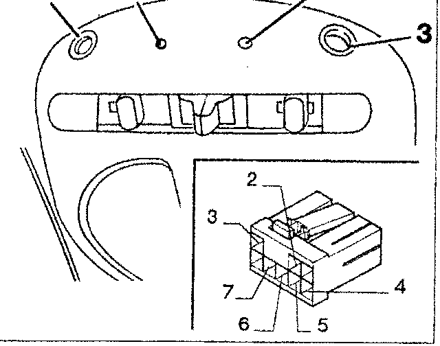
Detail of receiver on front courtesy light
- Green warning light (LED)
- memorization button
- Volumetric sensors
Receiver connector
- Not connected
- Serial line to alarm control unit
- Battery positive (+30)
- Earth
- Door unlock
- Door lock
- Ignition-dependent positive (+15)
- Not connected
REMOTE CONTROL
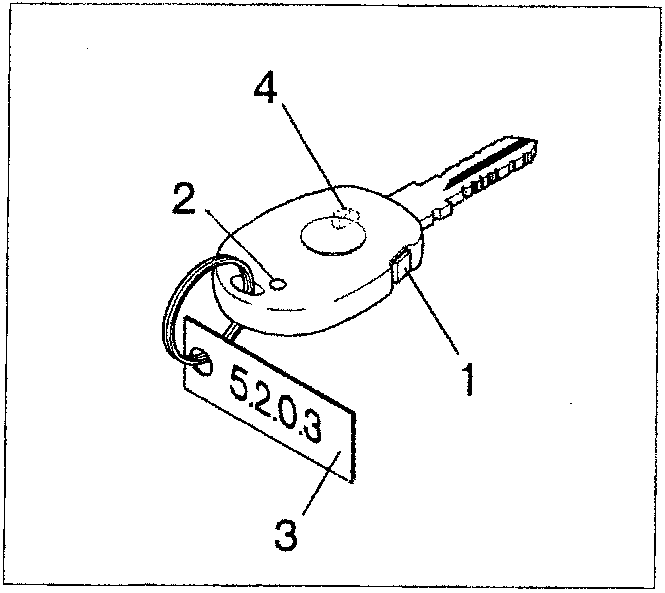
The alarm system remote control, built into the ignition key (figure opposite), is an electronic device which sends a signal to the receiver for controlling the opening/closure of the doors and activation/deactivation of the alarm system.
Whenever the button (1) on the remote control is pressed, the remote control issues a radio code which has a radius of action of about 10 metres.
- Control button
- Repeater warning light (LED)
- Access code (password) tag
- Transponder (for Fiat CODE - not visible)
NOTE If the control unit, receiver and/or remote controls are replaced, components from the same type of system must be used.
Parts & tools for this job For 1995 Fiat Bravo
- TOOLDigital multimeterSearch: automotive digital multimeter
- PARTAssorted fuse kitSearch: car fuse assortment kit
- TOOLWire crimper and connector kitSearch: wire crimper connector kit
Links open Amazon search results in a new tab. As an Amazon Associate I earn from qualifying purchases.