
123A
- Make
- Fiat
- Model
- Bravo /Brava (182) Factory Service Manual
- Year
- 1995–2001
- Section
- Connector blocks (2000 range) › 123A
55 Electrical system123A
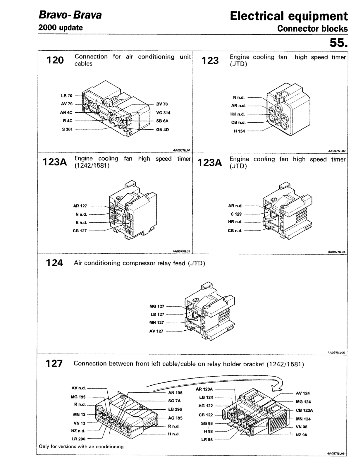
Connection for air conditioning unit cables
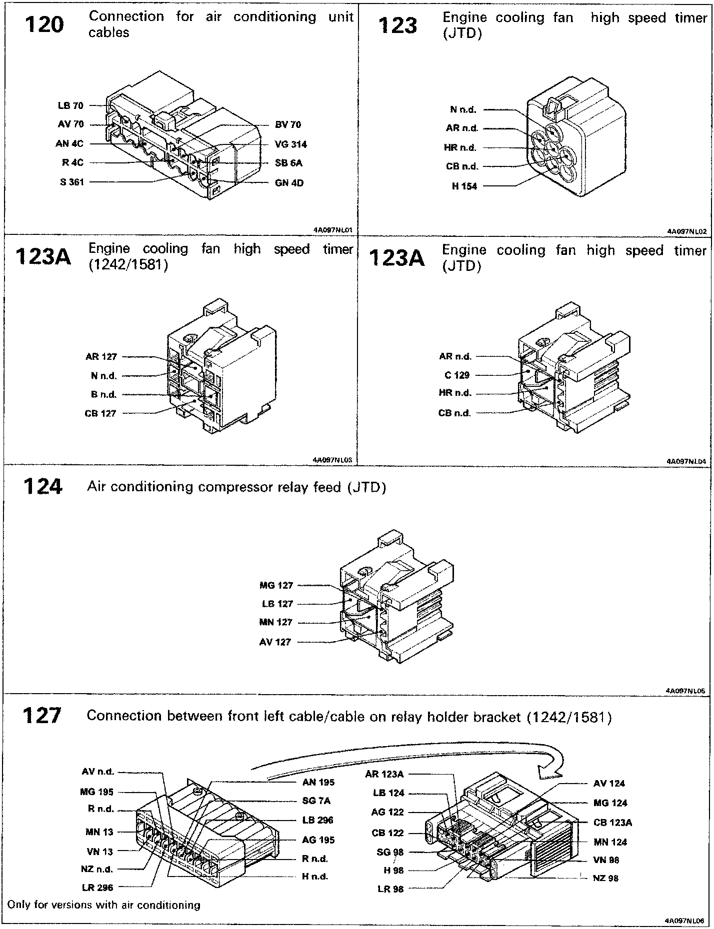
Engine cooling fan high speed timer (JTD)
123A
Engine cooling fan high speed timer (1242/1581)
123A
Engine cooling fan high speed timer (JTD)
Air conditioning compressor relay feed (JTD)
Connection between front left cable/cable on relay holder bracket (1242/1581)
Only for versions with air conditioning
Original page
Parts & tools for this job For 1995 Fiat Bravo
- TOOLDigital multimeterSearch: automotive digital multimeter
- PARTAssorted fuse kitSearch: car fuse assortment kit
- TOOLWire crimper and connector kitSearch: wire crimper connector kit
Links open Amazon search results in a new tab. As an Amazon Associate I earn from qualifying purchases.